Last Updated on 2026-03-23 by Daev Roehr
An electronics laboratory needs a modest amount of tools and equipment to be effective, and then you can go crazy from there. I’ll discuss the basic needs and then offer a peek into my own lab and equipment.
- First, have a keen awareness of the various hazards involved: High voltage, high heat, liquid lead (i.e. solder),toxic fumes, and a rather nasty opportunity for cadmium poisoning.
Next: - A well lit space with good ventilation
- A sturdy workbench with a durable heat resistant surface
- Storage – shelves, bins, boxes… can’t have too much storage!
- Hand tools:
- Screwdrivers, small socket set, hex and torx drivers, long nose and diagonal cutter pliers in multiple sizes… the list gets long quick!
Drill and bits, nibblers, reamers - Dremel tool with cutoff and grinding wheels
- Files, round, and flat
- X-ACTO handles and blades
- A magnifying glass with light (see pic following, right side)
- Soldering iron(s) – What I use: Lab: Soldering Iron
- Screwdrivers, small socket set, hex and torx drivers, long nose and diagonal cutter pliers in multiple sizes… the list gets long quick!
- Test instruments:
- At a minimum, at least one basic DMM.
VOM’s can’t be used for high impedance circuits, they will load them down and cause inaccuracies. Also make sure your DMM can handle high voltages in tube gear, at least 600 Volts. - An oscilloscope with appropriate signal generators is required for most audio and electronics tinkering.
- If you’re repairing vintage equipment, a capacitor checker that measures ESR is quite handy.
- Known good equipment. For example, I have an amp and speakers to use with my audio repair hobby.
- At a minimum, at least one basic DMM.
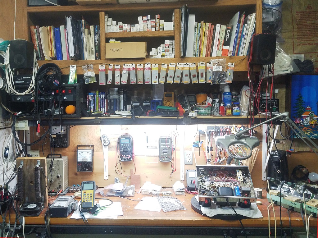
Here’s my shop bench, with the usual assortment of projects and floobydust on it.
My AC power “dim bulb” tester box
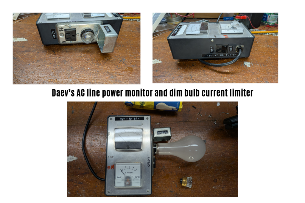
The shop style outlet with an Edison screw in fuse lets me swap the 150 watt bulb easily.
And my test equipment rack. (Yeah, I’m in the “crazy electronics nut” category.)
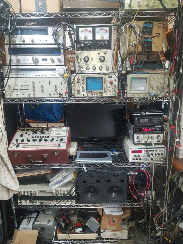
My shop equipment is heavily audio oriented. The centerpiece is an Audio Precision One, which is an older but still highly useful and accurate lab grade audio generator and analyzer. This older unit may not quite keep up with the latest ultra high fidelity analog and digital designs, but it’s more than adequate for the vintage audio gear I work with. It’s residual frequency response and THD (including cabling, connectors, and the breakout box for the oscilloscope) is quite low, as illustrated here:
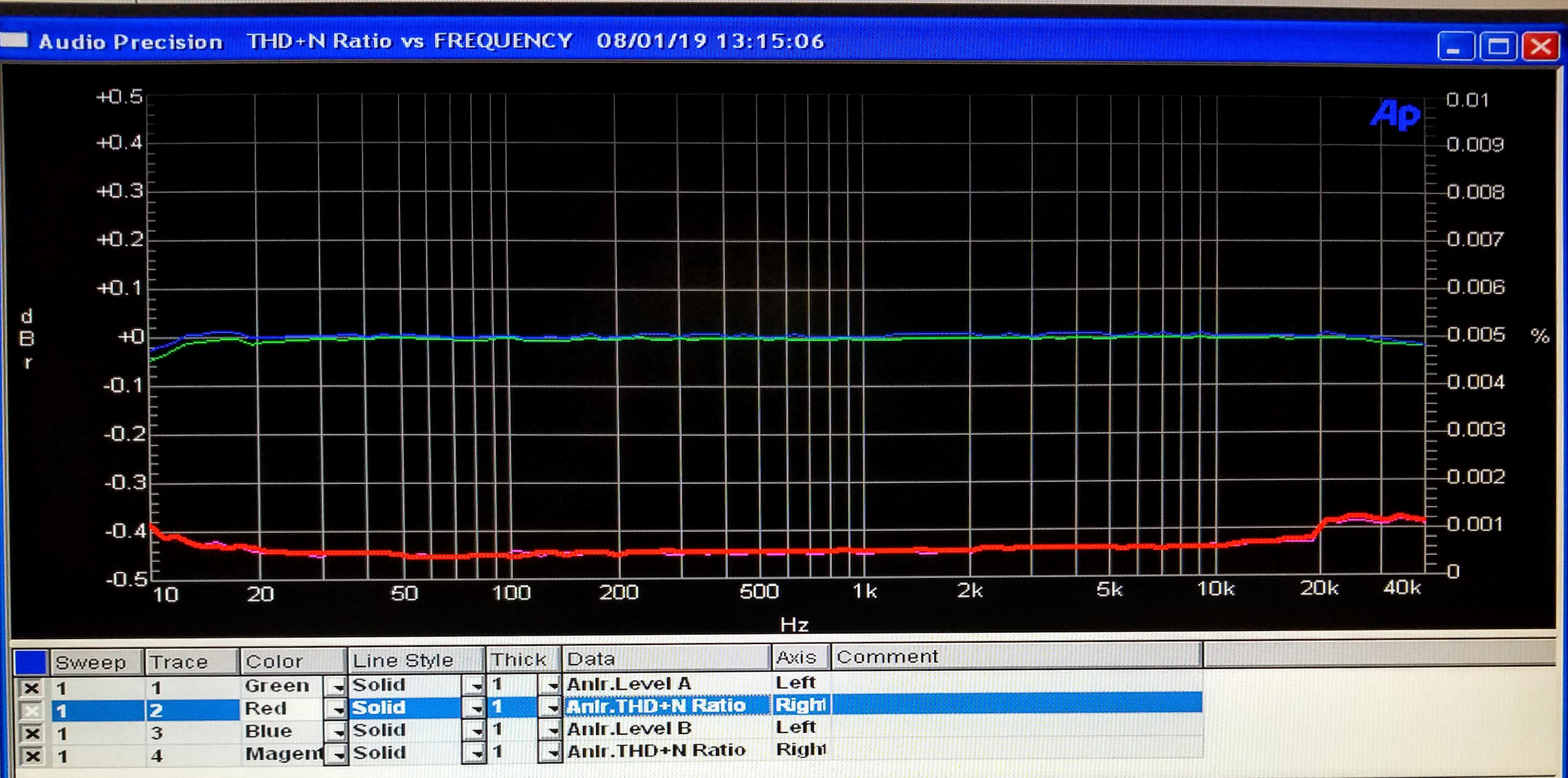
The blue/cyan lines are deviations from a flat frequency response on a scale of +/- 0.5 dB, left axis. The red/magenta lines are the total THD %, on scale of 0.000 to 0.010 %. Per the usual tech rule of thumb, this about a magnitude better than the equipment I’m servicing or evaluating,
This is a good place to touch on an important concept: knowing and testing your test equipment.
To make the previous photo, I plugged the output cables into my input test jig to verify all is well. Instead, I found one of my patch cords had developed a high frequency roll off error; now I have to redo much of my tube buffer amp research – Tube Audio Buffers. Ugh.
Another important concept is knowing your equipments’ limits. For example, a lot of modern equipment is only rated for 400 volts (or even 200!). Using such a device on a 500 volt B+ supply can cause severe equipment damage, not to mention arcing or fire.
Along with audio amps and pre-amps, I dabble with restoring AM and FM stereo tuners. The rack contains several of the highly specialized signal generators for both AM and FM tuners.
A more unusual tester shown here is the capacitor analyzer. When I rebuild old vacuum tube equipment, I often need to measure the leakage current at the full rated voltage. When you’re at 450 volts, a leaky capacitor can explode from the heat buildup! I also have an in-circuit ESR capacitor tester in the box.
Vacuum tube testers
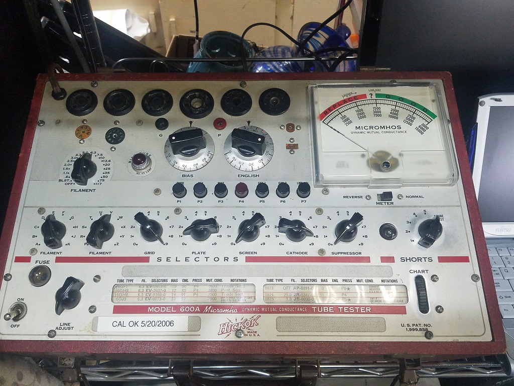
Check out this nice vintage Hickok 600a tube tester, one of several I use. Yes, these too must be rebuilt and re-calibrated after 60-80 years of use or disuse.
My other main tester, a B&K 700
(pic here)
See here for notes on this tester: https://tubesound.com/bk-707-tube-tester/
About Tube Testers
Tube testers fall into three general categories. From least to most accurate, they are: Emission testers, gM testers, and curve tracers.
And let’s not forget the intended application circuit, which might be thought of as the final QA tester).
The results you will get depend on what type of tester you are using and what you are looking for.
[ Keep in mind no tester will tell you how good a tube will perform in a particular circuit, the best it can do is weed out the malfunctioning and damaged ones, and perhaps offer a bit of insight into how much life it may have. ]
First up is the emissions tester, the cheapest and generally the least accurate of the bunch. It tests tubes as if they were simple rectifiers, not a very representative method for how tubes are typically used. Properly used however, this type of tester can weed out shorted or badly defective tubes, but that’s about it.
Typically inexpensive and found in drug stores of times past, they will often imply a tube is weak or in poor condition when they are not. The point was to sell replacement tubes, you see…
This tester is completely unsuitable for “matching” tubes, don’t go there.
Next up is the gM or micromho tester.
This is the typical service tester in use. It measures tranconductance in micromho’s, a much better indicator of general tub quality. However, it only measures with one set of electrical parameters, not a the full range the tube is designed for, so it will provide misleading quality measurements. It is generally unsuitable for tube matching, although with care it can work in some cases.
An interesting read on accuracy and repeatability by Chris Haedt March 2002:
https://www.bbtvtestequipment.com/chris-haedt—tt-differences
An interesting way to create a calibration tube: (Have not tested this myself)
(begin snip)
In the AVO VCM service manual, they describe how to check a new 12AU7 tube for use as a reference tube for checking the VCM’s calibration. The tests require the following, (the supply voltages should be within ±1%):
• A B9A tube socket
• A 200V regulated DC supply.
• A 6.3V, DC or AC supply (for parallel filament) or a 12.6V supply (for series filament).
• A variable DC supply for negative grid bias (stable and low noise, could be a battery and potentiometer).
Connect the tube base to the appropriate supplies, with the two halves of the tube connected in parallel. Set the grid supply to -9V, the HT to 200V and plug in the tube. Let the tube warm up for several minutes, and note the anode current.
Then adjust the grid supply until you get an anode current of 16mA. Note this grid supply voltage. The gm of the tube is equal to the difference in the two anode current readings, divided by the difference in the grid voltage readings. This gives you a tube with a known gm, that can be used to check the calibration of your tube tester.
(end snip)
Lastly, the curve tracer.
Properly used, a curve tracer can give you insight into how the device will behave under a range of conditions. These typically display a family of performance curves on an oscilloscope type display, hence the name.