Last Updated on 2026-02-03 by Daev Roehr
This page documents installing a new driver board into a Dynaco Stereo 70.
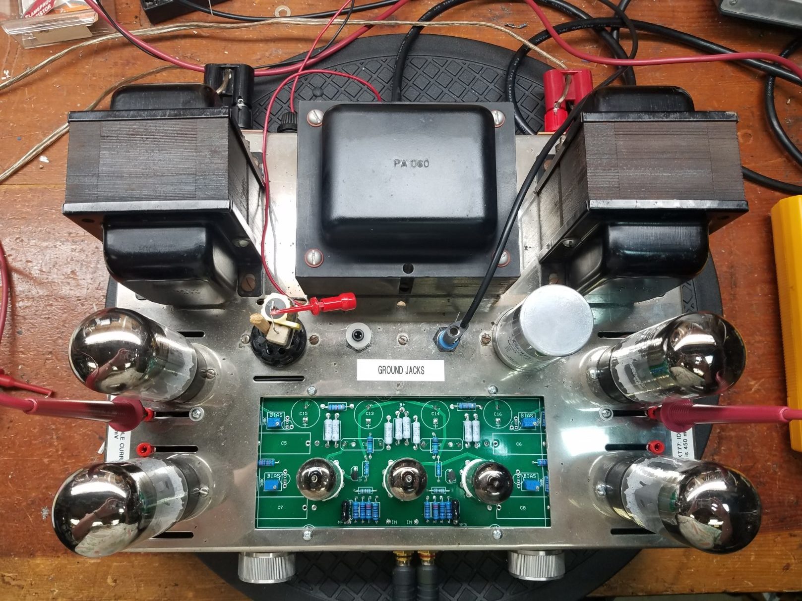
The finished unit
The VTA ST-70 driver board is one of many replacement boards for the popular but aging Dynaco Stereo 70 tube amp PC-3 driver board.
Read about it from the designer: http://www.tubes4hifi.com/ST70.htm
This new driver design is well regarded and well thought out:
– This newest iteration uses a 20mA constant current source (CCS) to get perfect AC splitter balance without trimming.
– The board has excellent L/R channel matching, something the original design had problems with.
– Uses 12AU7A/6189 tubes in place of the problematic and long out of production 7189.
– It cleans up the under chassis wiring considerably. The negative voltage bias supply and the 4 trim pots to set idle current (bias) are all onboard now. The separate trimmers negates the need and expense for closely “plate current matched” output tubes.
All in all, a highly recommended upgrade to this venerable design.
P.S. This is also a perfect time to do the small amount of rewiring needed for a lower noise star ground system upgrade, documented in detail on my Stereo 70 page.
PCB Build tips:
The PCB assembly notes are simple and clear and the PCB is well made and clearly labeled so it goes together quickly.
– For a pro look, arrange the resistors to read in the same direction, and make sure the capacitor values are visible.
– Space all power resistors off of the board about 0.1″. This avoids burning the board and allows max air cooling for the resistors.
– The supplied idle current trimmers (or bias voltage, if you prefer) are a bit twitchy for my taste, I swapped them out for multi-turn pots. The ones I used are 50K cermet 12 turn Bornes units, rated at 250mA. Note they fit perfectly in the current boards, but are “backwards” from the VTA stock units. IOW, a CW rotation increases the negative voltage resulting in less idle current (cooler plates).
– I chose to put the electrolytics and coupler capacitors on the bottom side of the board to get them away from the the heat of the tubes. (See pics below)
– Capacitor upgrade: I’ve long been a fan of Solens caps for couplers in Dyna tube amps, and using larger values from the stock ones will help flatten the bass response from the stock values. Here, I used 2 for the 0.1uF driver to phase splitter couplers and I used 4 1.0uF for the ‘splitter to output’ couplers.
Chassis top view
Observe the old chassis mount bias pots are unused and removed with this upgrade. I put a banana and a pin tip jack to fill the holes, wired to the star ground point. This is useful for setting the idle current, bench testing, debugging ground loops, and so forth.
Visible here in the the 5AR4 socket is an experimental SS rectifier plugin module with two 1000 PIV diodes and a 50 ohm, 10 watt series dropping resistor. As the AC mains thermistor reduces the power on surge and thus provides a slow start, a SS rectifier should now (in theory) now be a perfectly safe alternative to an expensive NOS 5AR4. Wiring the socket this way permits quick swaps for SS to tube comparisons or rectifier testing. If you decide to play with this, also place a 0.01 uF 600 V capacitor at the first stage filter to ground to reduce SS diode switching noise and hash.
Also added are the 4 red pin jacks for easily measuring the per tube idle current. They are installed in the end of the cooling slots (I had to hog them out a bit).
Chassis – Underside View 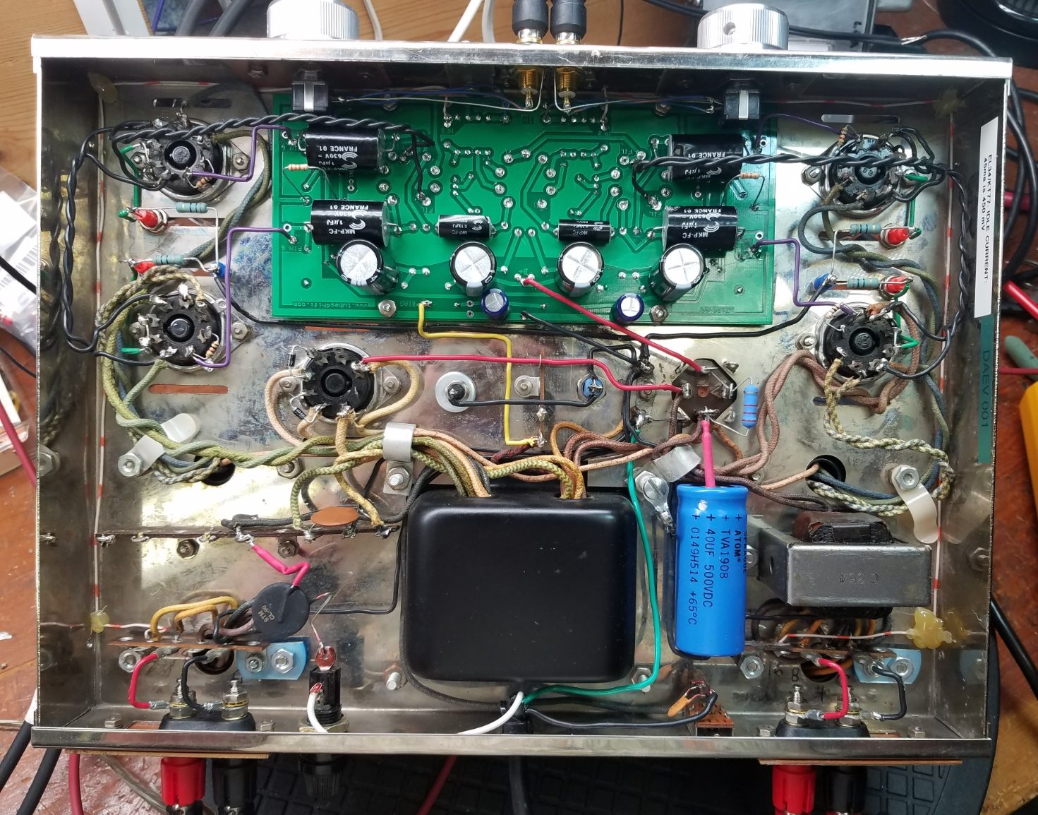
You can see the under PCB capacitors, bias test point pin jacks, cleaned up wiring, and a few other safety and reliability mods in this photo. Refer to my general Dynaco 70 page for more details on the mods: Vacuum Tube Audio – Dynaco
Valves/Tubes/Bottles…
I ordered some NOS 6189’s (mil-spec version of 12AU7/ECC82) from AES. While they were in transit, I used some old 12AU7’s I had laying around. (They measured fine on my Hickok 600A tester.)
The rectifier tube is one of my precious original vintage Mullard and the EL-34 outputs are new, current production JJ’s. On first power up, everything looks good, the amp biased up to a 40mA idle, and a sine wave looked clean.
After about 1 hour of run-in, here’s what THD vs frequency looks like at 1 watt. 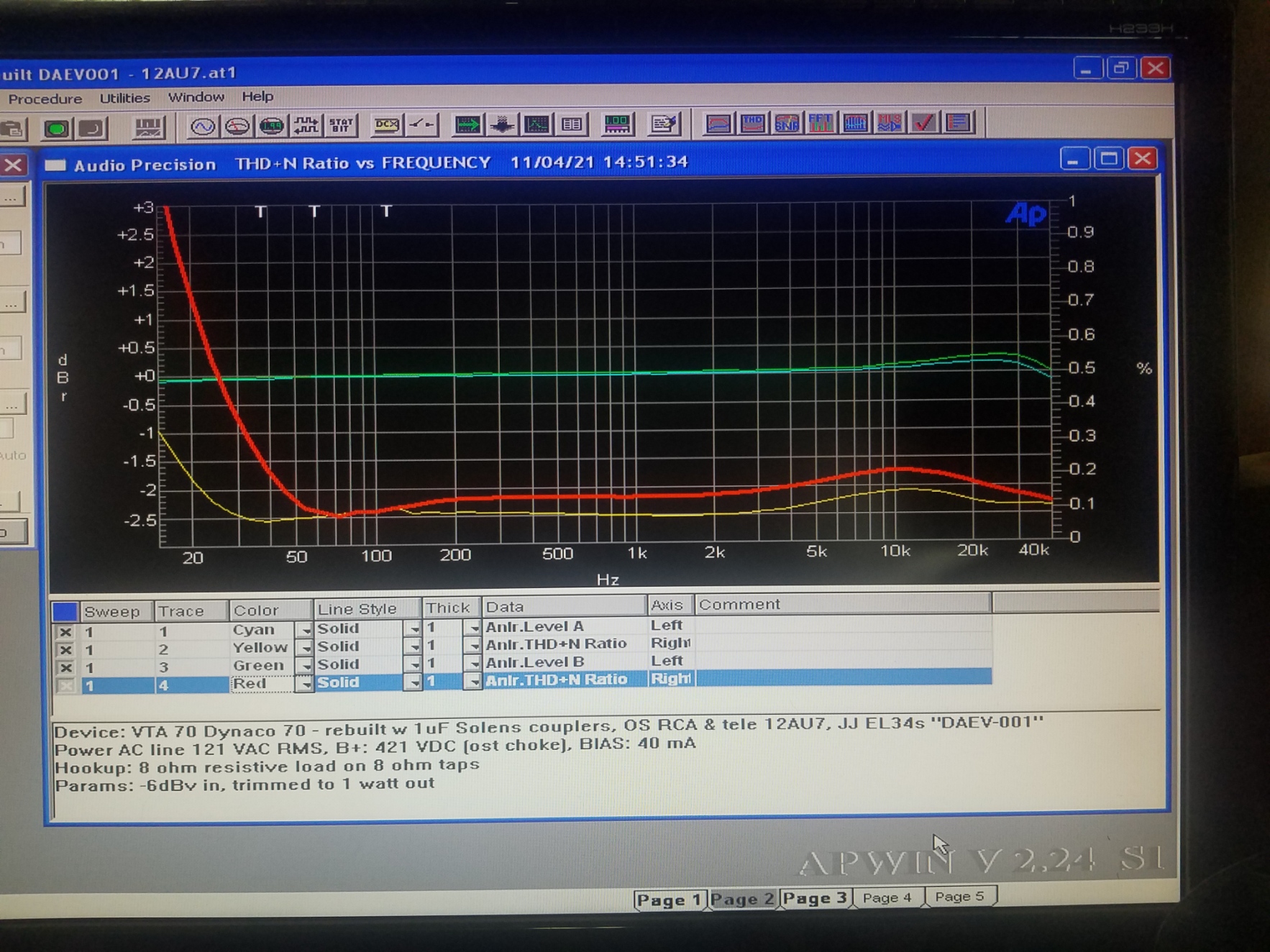
THD vs power: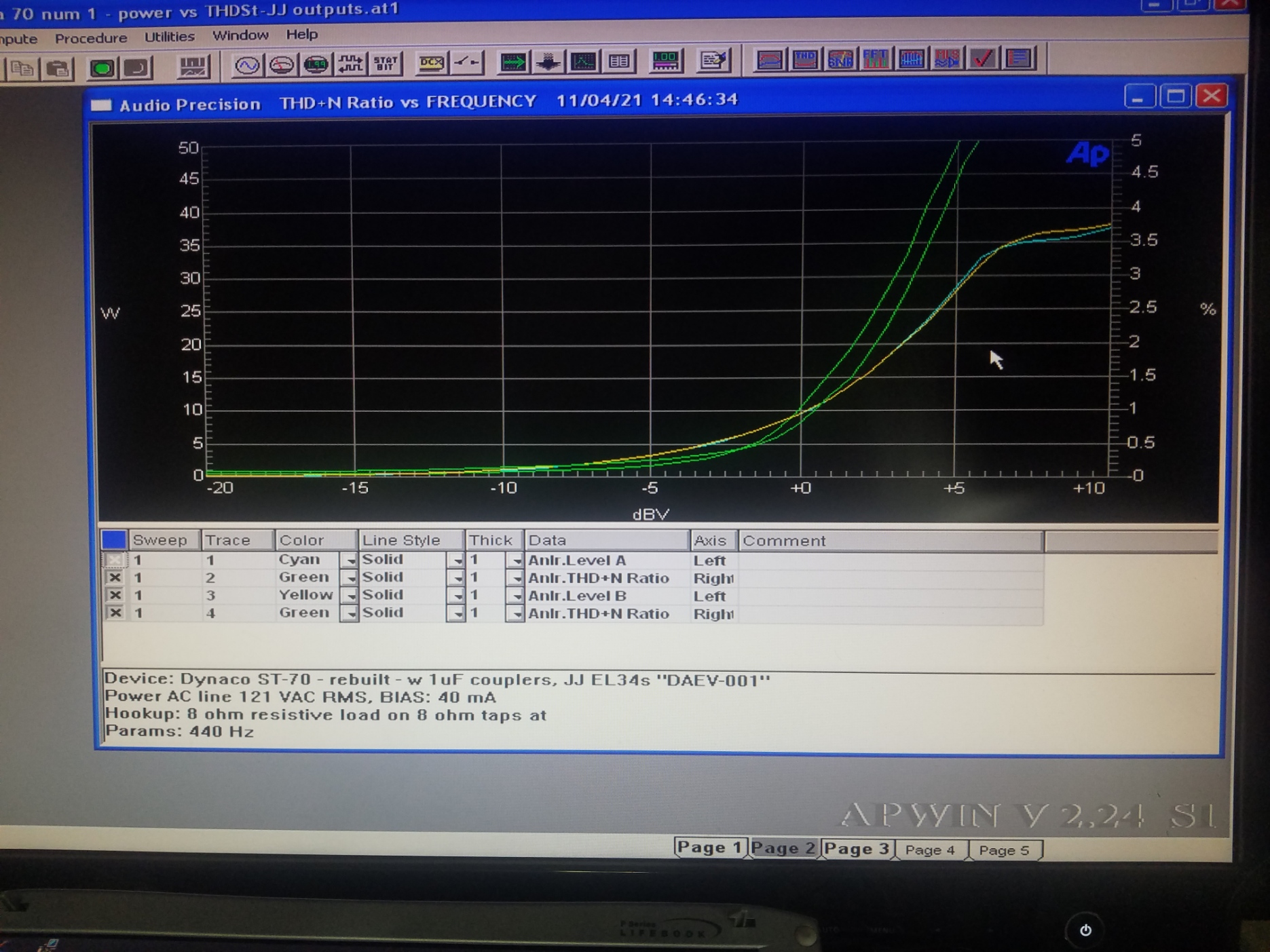
Some scope photos…
Square waves at 2 watts looks like: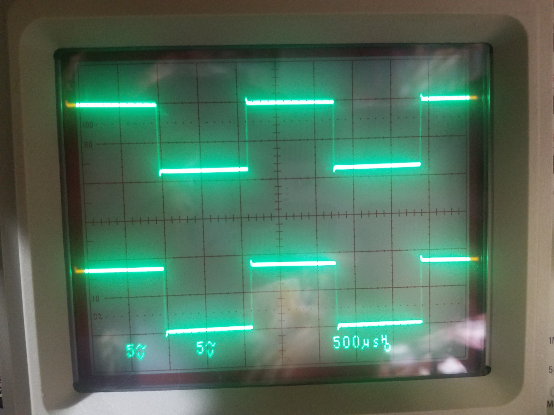
Dyna/VTA-70 at 2 watts, 440 Hz
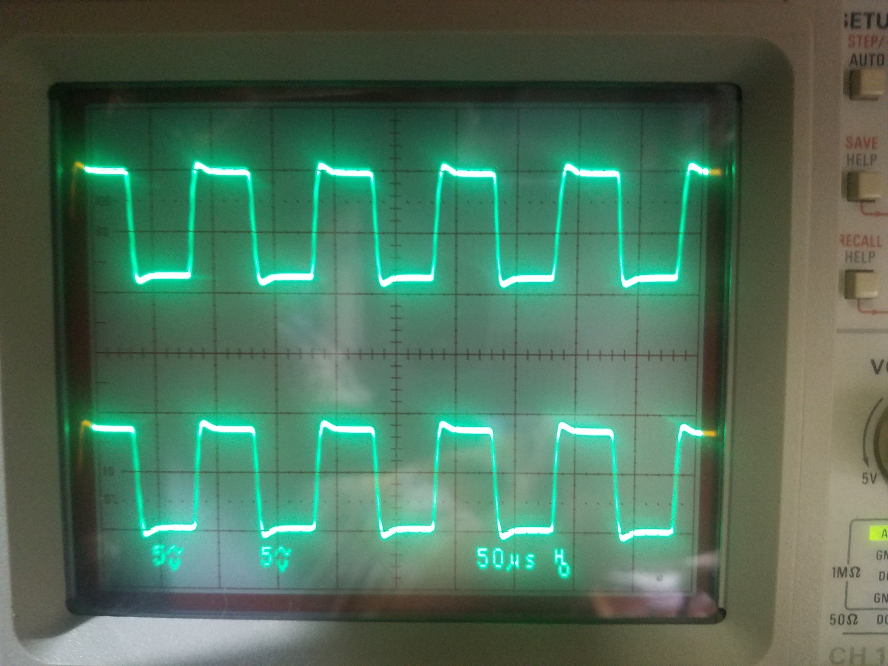
Dyna/VTA-70 at 2 watts, 10kHz
These are good results overall. The difficult square wave test shows a tiny bit of overshoot at 440 Hz, and the 10 kHz pattern is quite good too.
The THD is a tad higher overall then I would like, especially in the right channel at low frequencies. I’ll recheck when the 6189 tubes arrive, but this is probably the output tubes being under biased a bit.
2021.11.05
Yay! The 6189s arrived (thanks AES!), and I also upped the idle current to 45 mA per tube.
This combination yields this sweep of frequency vs THD response at 1 watt
The frequency response scale is +/-1 dB (left side numbers)
The THD scale is 0 to 1% (right side numbers). 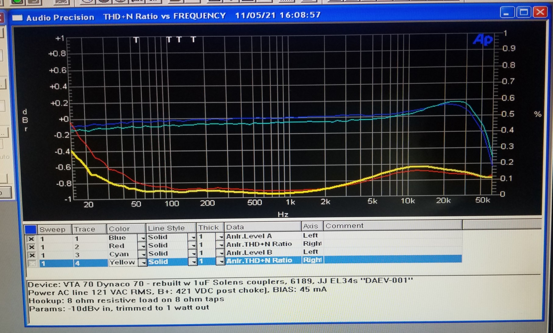
These measurements are now quite good.
The THD is under 0.05% over the critical midrange, and under 0.2% overall except below 30Hz. The rising THD at extremely low frequencies suggest there’s still a bit of strain in the low bass, I would recommend a subwoofer and an active crossover between 80 and 50 Hz.
The amp draw about 160 watts while idling, not a bad sounding heater! 🙂
2021.11.26 – Next up:
The B+ rectifier
Comparing the SS rectifier module to a real “old stock” Mullard 5AR4 rectifier for the B+
Replacing a tube rectifier with a SS rectifier isn’t just a simple direct swap.
Some things to consider are:
– Silicon rectifiers have considerably less forward voltage drop than tubes, meaning your B+ will be too high. This must be dealt with, else a dangerous overvoltage will occur.
– 5AR4’s are a slow turn on rectifier tube, which is theoretically less stressful on the high voltage system and tubes. Opinions are mixed as to just how important this is, but a softer turn on is clearly less stressful overall and doesn’t hurt anything.
– The rectifier’s heater takes a hefty 1.9 amps at 5 VAC (9.5) watts. Removing that load from the power transformer theoretically should make it run a bit cooler, and again can’t hurt anything.
For this experiment:
– I already installed a thermistor on the transformers primary which should address enough of the potential turn on surge issue, as well as dropping about 2.8 VAC on the primary.
– I already installed the 1000 PIV plate series diodes to address the PIV issues with the less rugged, current production 5AR4 tubes.
I built my SS rectifier jig on a tube plug with 1000 PIV diodes and a 50 ohm, 10 watt series resistor, thereby allowing a quick swap with a tube rectifier. As usual, I’ll first measure first and listen later.
This turned out to be quite important, as the scope showed an increase in the noise floor, the cause turned out to be silicon diode switching noise. Such noise is easily easily cured by placing a 0.01 uF 600 v cap on the first B+ cap to shunt the noise to ground. That dropped the noise floor to less than 500 mV, which is acceptable for my purposes.
A quick check showed no increase in THD or S/N, and the power output vs THD looks to be the same too. Good enough for now, more measurement and listening tests later.
Comparing output tubes:
New EL-34, KT-77
Vintage 6CA7 GE “fatboys”
JJ KT-77’s
The first wrinkle was the KT-77’s wouldn’t bias up high enough with the stock VTA bias circuit to get up to my currently preferred 45 mA idle current. I’ll reduce the ground resistor to get enough range from the pot. Also, the bias adjustment already feels a little too twitchy with the stock bias trimmers, so I’ll replace them with multiturn units while I’m in there.
2021.11.30
Done with bias circuit mods.
– Tacked a 33K across the existing 27K bias-pot-to-ground resistor, which makes R37 & R38 about 15K. This increases the the bias voltage range from the stock range of {-60 / -34} up to {-60 / -24} VDC, which now allows KT-77’s to be biased up warm enough to use.
The multiturn pots I used are 50K cermet 12 turn Bornes units, rated at 250mA. Note they fit perfectly in the current boards, but are “backwards” from the VTA stock units. IOW, a CW rotation increases the negative voltage resulting in less idle current (cooler plates).
KT-77 quick tests
Frequency vs THD at 1 watt, 8 ohm load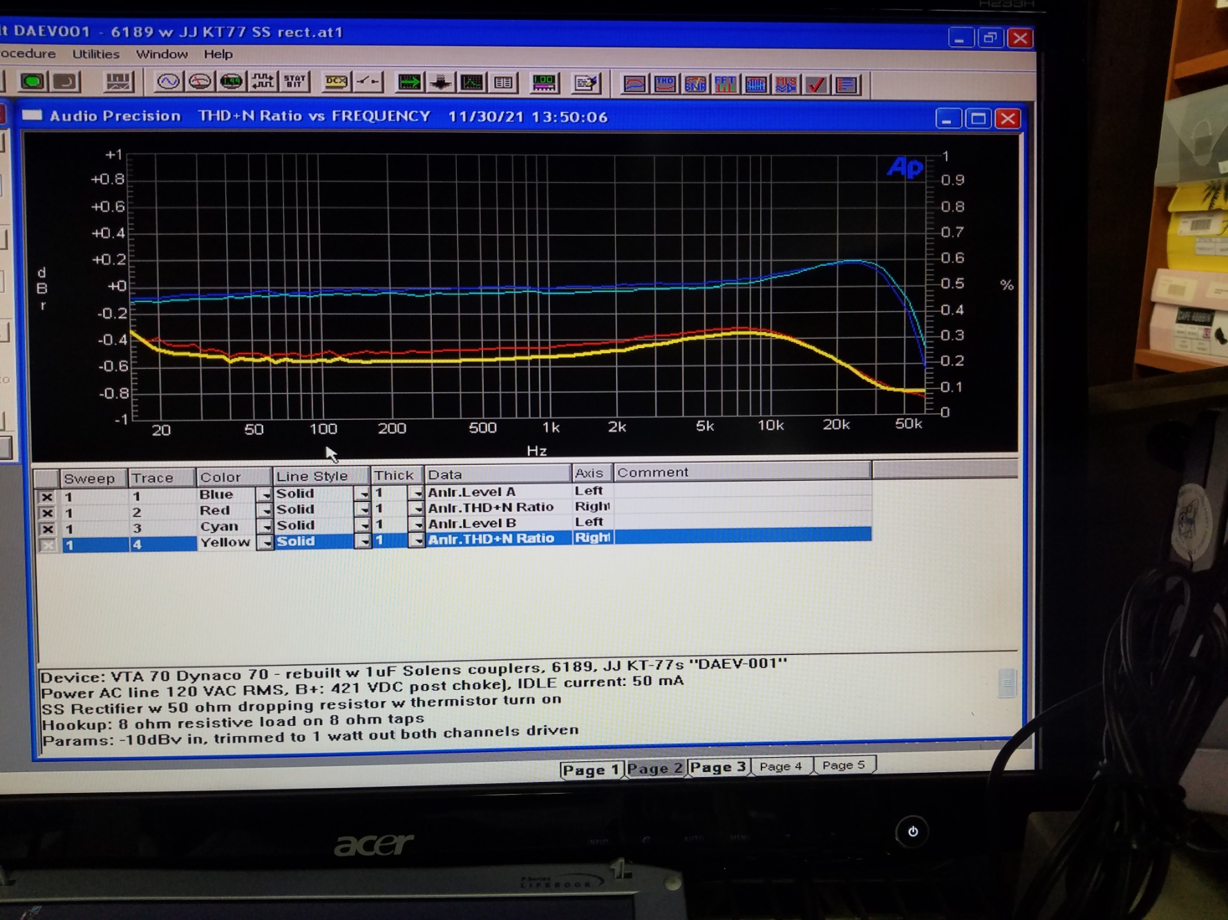
Power output vs THD – The KT-77’s have an odd kink (yellow and red) in their THD vs power response.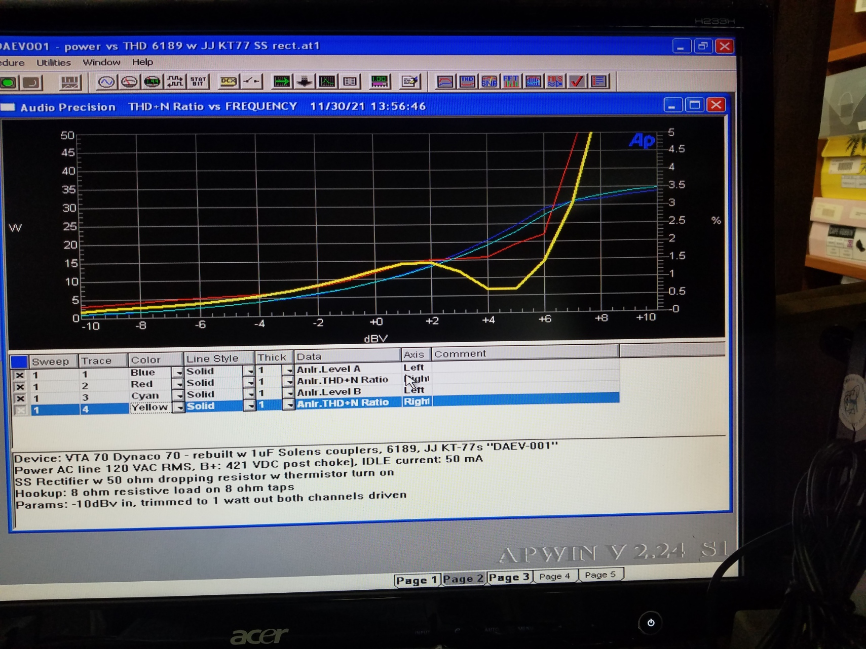
And here’s the spectrum analysis. Fairly rich in second and third harmonics, but I’ll need to re-run the EL-34’s for a better comparison.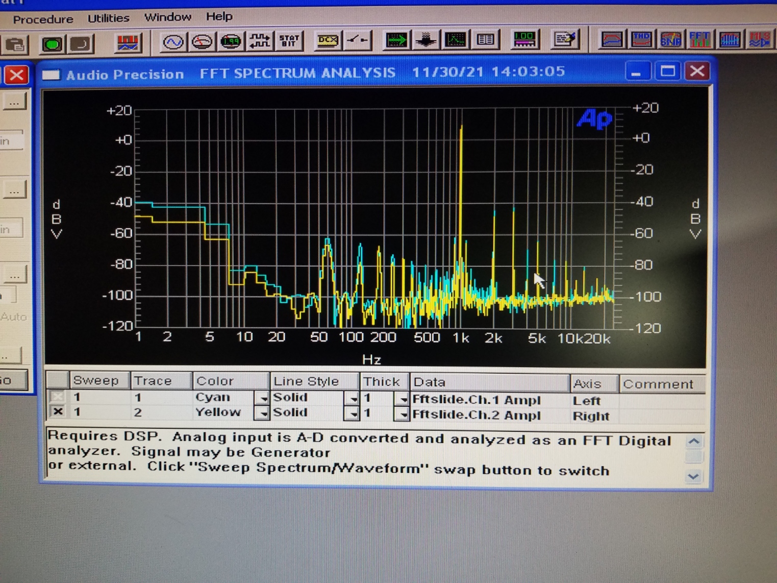
KT-77 summary: Frequency vs THD is about 0.1% higher THD on average than the EL-34’S, even after I biased the KT-77s hotter at 50 mA. The THD is over 0.2% over the entire spectrum, and peaks up to about 0.35% at 7 KHz. Doesn’t seem like the best match for this unit so far. I assume the listen only crowd will call this a “warm” sound.
Tests with 6CA7 vintage GE “fatboys”
Here’s the charts with the old stock 6CA7’s
Frequency vs THD at 1 watt, 8 ohm load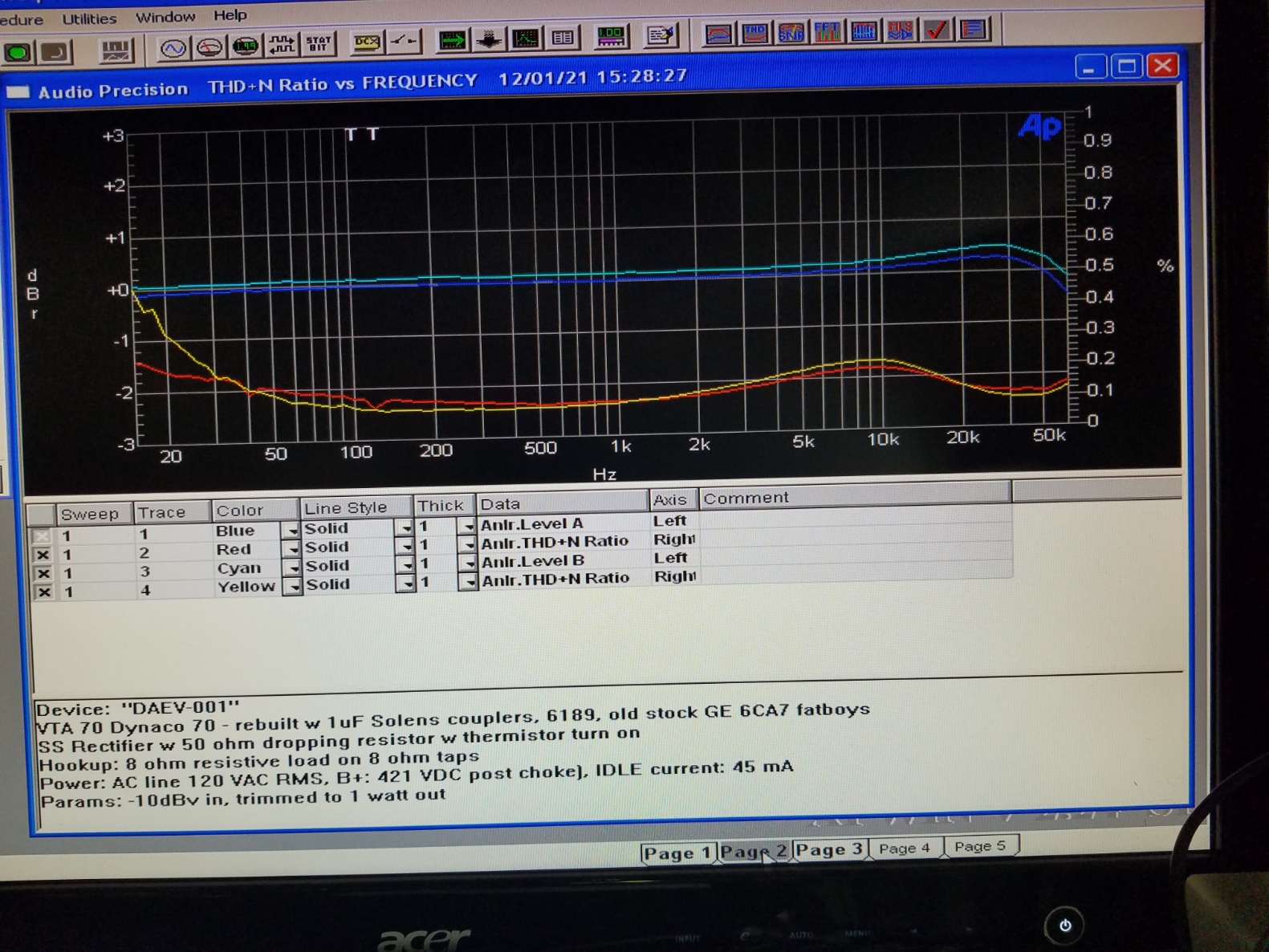
Wow, these 50+ year old output tubes still measure really well!
I think I have some old stock 6L6’s laying around, will test them soon!