Last Updated on 2026-05-06 by Daev Roehr
Dynaco Amps, Tube Preamps, and Tuners – rebuilding and modification investigations, oh my!
(Incept date: 2020.11.19)
But first…
Consider this the usual safety disclaimer:
High voltage is very dangerous, I’m not liable for any damage of you, or your gear, or your house, or anything. This is just advice, it’s worth what you’re paying for it, etc. There’s lots of information on high voltage safety; find it, read it, understand it, practice it. There is also the unit’s safety to consider. Many of the key parts are no longer available, so don’t melt or smoke your amp!
Next, there are already lots of pages on Dynaco history and rebuilding stuff, I won’t repeat or compete with them here. Instead I’ll be looking at some of the common mods for these interesting vintage units, mods for both safety and performance.
I’ll also mention/debunk a few mods you should *not* do, and explain why.
Lastly, this page is really my lab notes while I’m working on these mods. As such, the information may change as I learn more, make interesting discoveries, or prove a theory wrong. I’m mostly making this for myself, so in twenty years I can look back and find out why I did something. Or not. 🙂
My philosophy on modifications
There are many ways to look at modifications: to improve performance, increase safety, improve reliability, to add a feature, etc.
My general philosophy is “Firstly; do no harm!”
Classic amp modifications should be done in such a way that they can be undone, else you’ve permanently altered a bit of history. That means not cutting new holes in, nor repainting, the chassis or faceplates, nor radically altering the circuit.
That last point (altering the circuit) can be a bit flexible in the case of a Dynaco ST70, for these reasons:
– These amps are not scarce. There were very popular, with at least 300,000 sold.
– Some portions of the design haven’t aged well. The original ST-70 driver circuit board is prone to old age rot and getting burned from the driver tubes. And speaking of drivers, a key issue is the increasingly awkward 7199 driver tube availability problem. This tube is difficult to find any price, much less good NOS ones. There are some fine replacement boards with improved sound and circuitry using readily available driver tubes. (In this case, a replacement driver board should also mean you keep the original driver board for the next owner. IMHO.)
I tend to be more science based and less “magic wire and caps” based while doing modifications. Science based in that the mods have to make sense based on design, then before/after measurements should reflect that. To that end, I have a fairly complete audio lab I use to objectively evaluate these changes.
After the science phase, I’ll listen subjectively to ensure it still sounds good.
For listening, I have these speakers available:
Klipsch Heresy III’s
Sound Dynamics RTS-3B1’s
NHT M-10 studio monitors
Pioneer SP-BS41RL’s
DA PS10a’s
AR ??
Alesis point sevens
ADS 200
It’s important to note a modification should have a “before” and “after” phase, otherwise how will you know your mod is actually worthwhile?
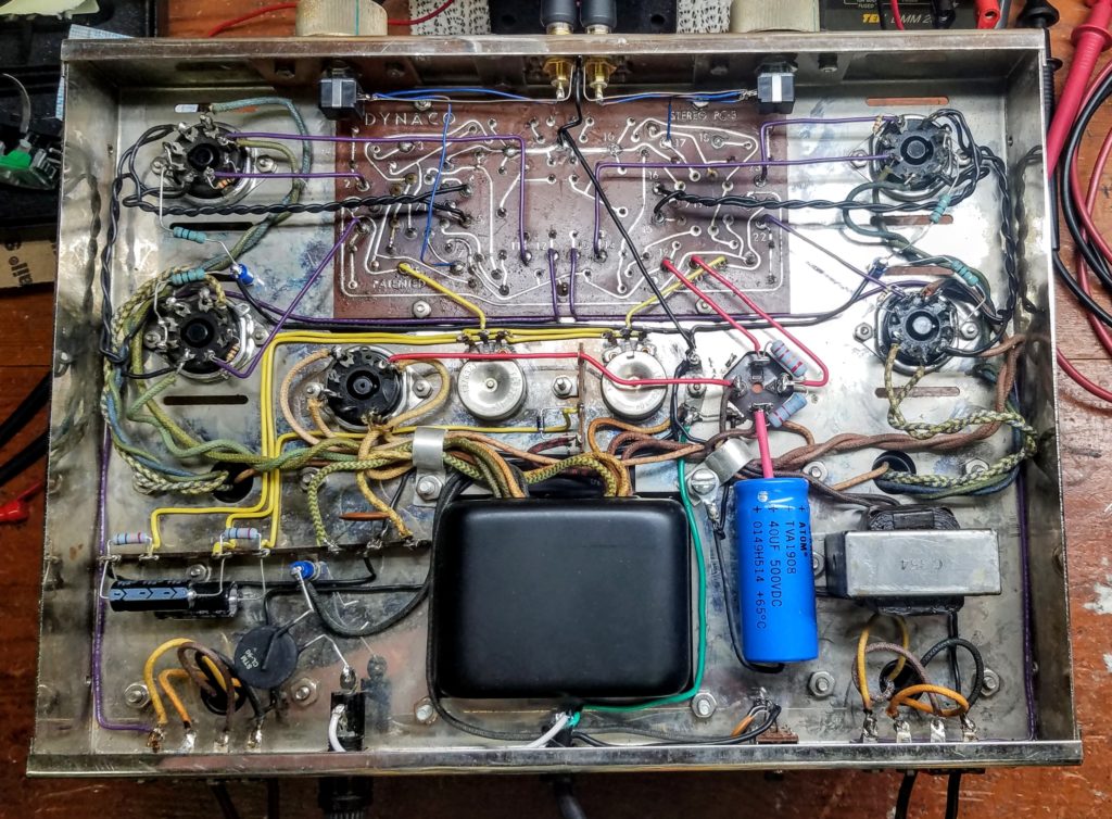
Restored Dynaco ST-70 testbed amp
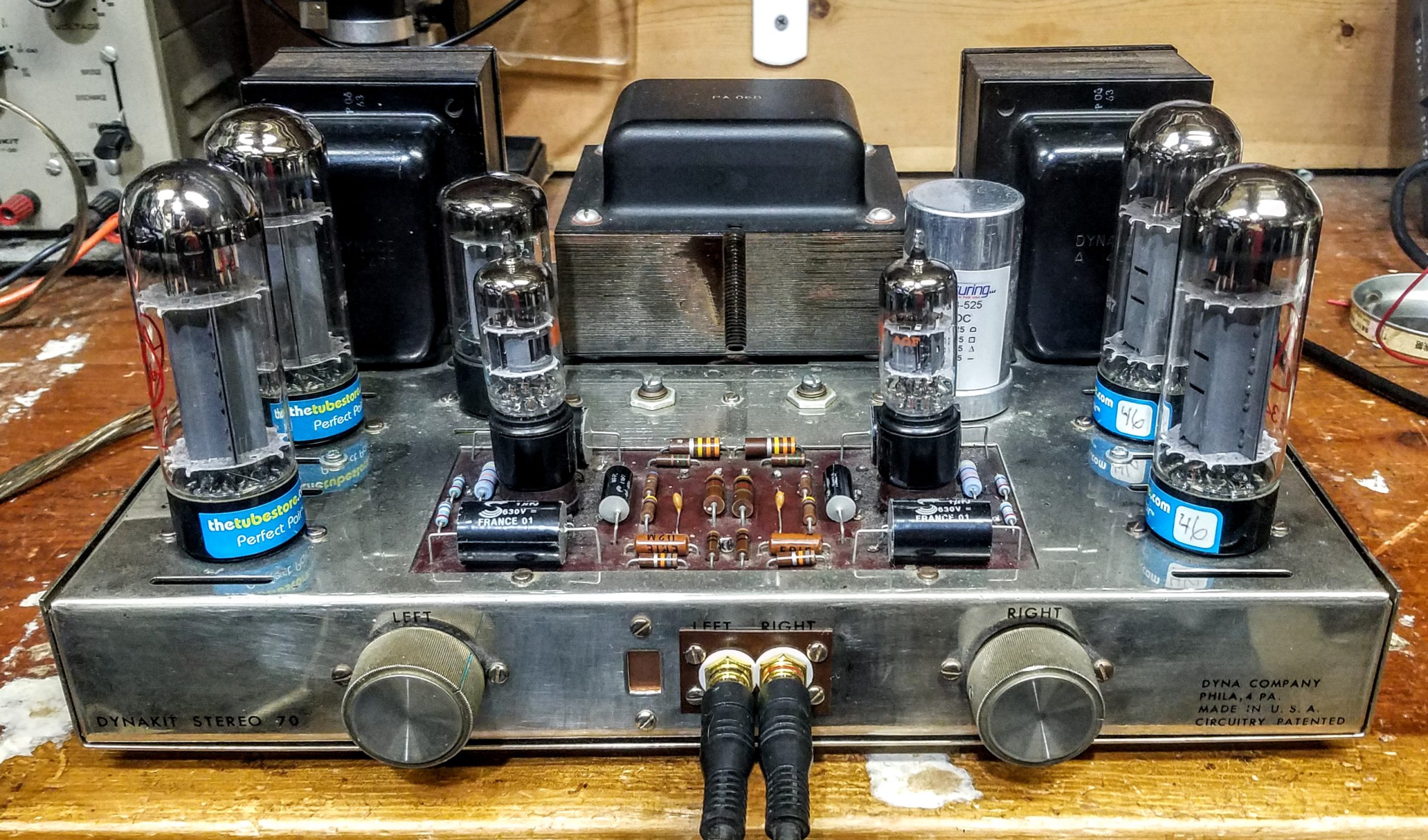
A refurbished amp, ready to rock!
This amp has what I consider the “essential rebuild” checklist items done:
- Tubes tested on a mutual conductance tester.
- All four output tube couplers and and the two pentode input grid capacitors replaced on PCB. This rebuild item is really important. Old leaky capacitors will increase the idle current (i.e. reduces the bias voltage) and that can cause catastrophic tube or transformer failure. I typically increase the capacitor values for better bass response (the originals caps were undersized): the 0.1 output couplers to 1.0 uF/ 600V and the input grid 0.05 coupler increased to 0.10uF, 600V.
- Check the AC fuse is actually a 3 amp slo-blo. (Can use a 2.0 amp fast-blo if you install the recommended thermistor inrush current limiter mod, described later).
This is very important!
As these units age, the idle current creeps up and up, eventually blowing the fuse. Uninformed owners will often put in bigger ones rather than source the issue, and the resultant overcurrent will melt your transformers. Expensive! - Tube sockets cleaned and re-tensioned, replace as needed.
- Power cord replaced with a 3 prong safety grounded cord and the ground tied to the amp chassis.
- Add 0.01uF, 1kV ceramic snubber cap added across power switch contacts. This helps keep the switch contacts from getting burned.
- Rebuild bias supply. The “eventual failure guaranteed” selenium rectifier s/b replaced, negative DC bias circuit completely rebuilt (new resistors and capacitors), including the “matched” 270K pairs on the PCB.
- Rebuild B+ supply, replace filter capacitor(s) and R/C filter resistors.
- Plate resistors replaced. Old ones often cause spitting or popping noises.
- Replace any other part that is out of tolerance.
Finally, proceed to a careful first power up with a variac. (My general variac suggestions are later in this doc.)
Here are the ST-70 amp mods I’ll be looking at:
- POWER SAFETY: Grounded AC mains
- GROUNDS: Change wiring to a star ground. (reduces 60 Hz hum and 120 Hz buzz)
- POWER: Diode pre-rectifiers for 5AR4 (unit safety) – “Yellow sheet Mod”
- POWER: Thermistor soft start (stress reduction)
- SIGNAL: 6GH8A vs 7199 drivers (convenience)
- SAFETY, BIAS: Use low wattage “fuse” resistor for cathode current measuring resistor (unit safety)
- SAFETY, BIAS: Adding a separate bias control for each output tube (unit safety)
- SIGNAL: Adding an input level trim (convenience)
- OPS: Running a ST-70 amp in true bridged mode (double the power)
- OPS: Running a ST70 in “triode” mode (half the power)
- TECH: Changing the feedback loop:
– to the 8 ohm tap
– changing R/C values
(Could yield lower distortion, better slew and frequency response.) - TECH: Changing cap values:
Coupler caps (4) to 1.0 uF, grid capacitors (2) to 0.10 - SIGNAL: Installing dual banana speaker output terminals
- SIGNAL: Moving RCA/Cinch jacks to the back of the chassis
- UPGRADE Replacing driver board with the VTA-70 PCB http://www.tubes4hifi.com/ST70.htm
( NEW for 2021 – VTA ST-70 CCS upgrade – a whole page on this ) - POWER: Replacing the 5AR4 tube w a SS rectifier
- Same amp, diff output tubes. JJ EL-34, JJ KT-77, vintage 6Ca7 “fat boys”, 6L6GC, 5881, //?
Some mods you *shouldn’t* do…
- More capacitance on *first* stage of B+. (Later stages OK)
- Regulating the negative bias supply
#ModMyths
Examining some common beliefs
- Modern AC line voltage is too high for these units, so some AC line voltage must be dropped.
#ModMyths
ST-70 amp mods and investigations
1. Power Safety
Grounded Chassis via AC Mains
Power cable to the chassis ground is all about safety. Your safety, to be precise.
Signal wiring grounds are all about minimizing noise and hum.
These are not the same thing, and this less than precise nomenclature of “ground” further clouds the issue.
Here’s a good overview on the complexities of this topic: https://www.diyaudio.com/forums/diyaudio-com-articles/163575-audio-component-grounding-interconnection.html
tl;dr:
Safety grounds reduce the chances of electrocution. Google “musician electrocution” if you are skeptical.
Signal grounds work to minimize ground loops and other undesirable noise.
Note that implementing the safety ground may expose system ground loops and other signal wiring weaknesses you’ll need to resolve as well. But it’s worth it, from both a safety and a lowered noise floor perspective.
I recommend this mod be combined with a latching off GFCI unit for best protection and safety. (see below)
Implementing a safety ground is easy!
1) Remove the old power cord and inadequate grommet.
2) Install a 3 conductor AC mains cord and a crimping strain relief grommet.
3) Attach the green ground wire to the chassis with a crimp on ring lug and star washer.
Note the safety ground point isn’t quite to international code, but If you add a star washer under the topside screw head for better “bite” at the ground point, it’s a pretty good retrofit. For extra safety protection, also plug into a GFCI outlet or adaptor.
2. GROUNDS
Rewire signal and power supply wiring to a star ground
These simple changes to the wiring of a ST-70 to will easily implement a signal path and a power supply star ground system. These units are pretty close already, so this is quite straightforward to do.
In 2025, I did this on a pair of Dynaco Mark IV’s, the low frequency and hum noise floor dropped some 12dB ! Post change, the output noise was a miniscule 500 uV ( i.e. 1/2 millivolt). A pair of headphones (Sony 7506) directly across the speaker terminals were silent as well.
Input signal ground changes
Replacing the input jacks requires some tinkering to avoid drilling new holes in the chassis, something I strive for. I discovered the phenolic insulator from the old jack pair could be easily “hogged” out a bit and reused to mount the new insulated gold RCA jacks.
The key thing is to ensure the jack ground doesn’t touch the chassis anywhere, as that will defeat the star ground right off the bat. As an added bonus, you can get the jacks a tad further apart (from 3 to about 6 mm), enough to now accept most modern RCA/Cinch style audio cables.
(On another day, I’ll investigate moving them to the back panel where they belong.)
Also shown is volume trims in the ugly PTO socket holes. I use a bit of PCB (or brass plate) cut to cover the socket hole and give the pot a place to be mounted. Add some real vintage Dyna knobs from a parts unit, it looks almost factory!
Next, clean up the cathode resistor grounds. They get pulled off the socket ground tabs and get their own wires to the star ground point via a standoff turret. (see next pic)
Lastly, the speaker tap grounds gets their own dedicated wire too, of course.
Power supply ground changes
The B+ is already wired correctly, and the filter can is at the main ground point already too. Just make sure the bias supply and the filament center tap gets their own connections too.
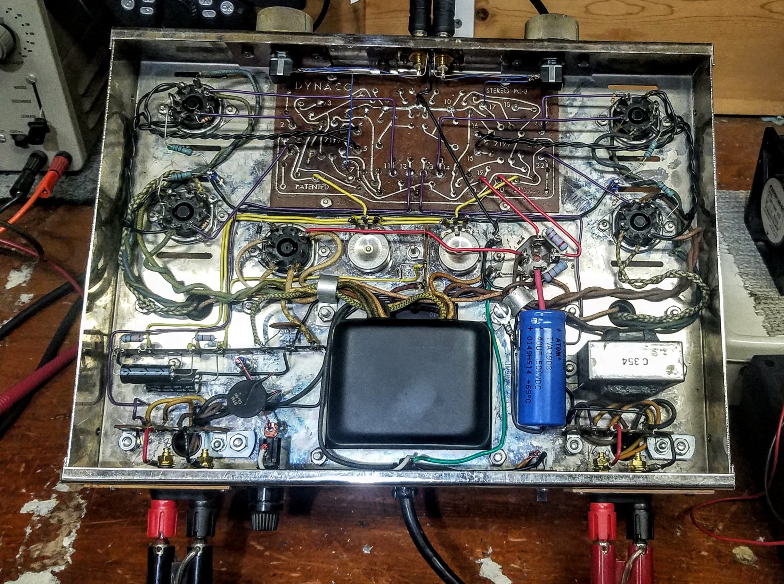
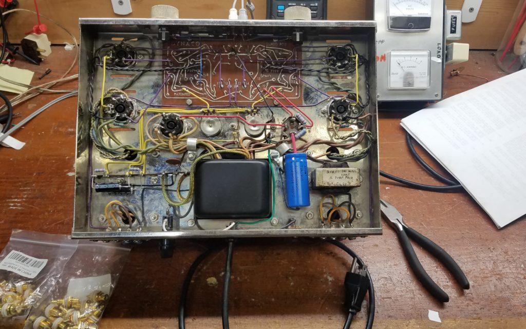
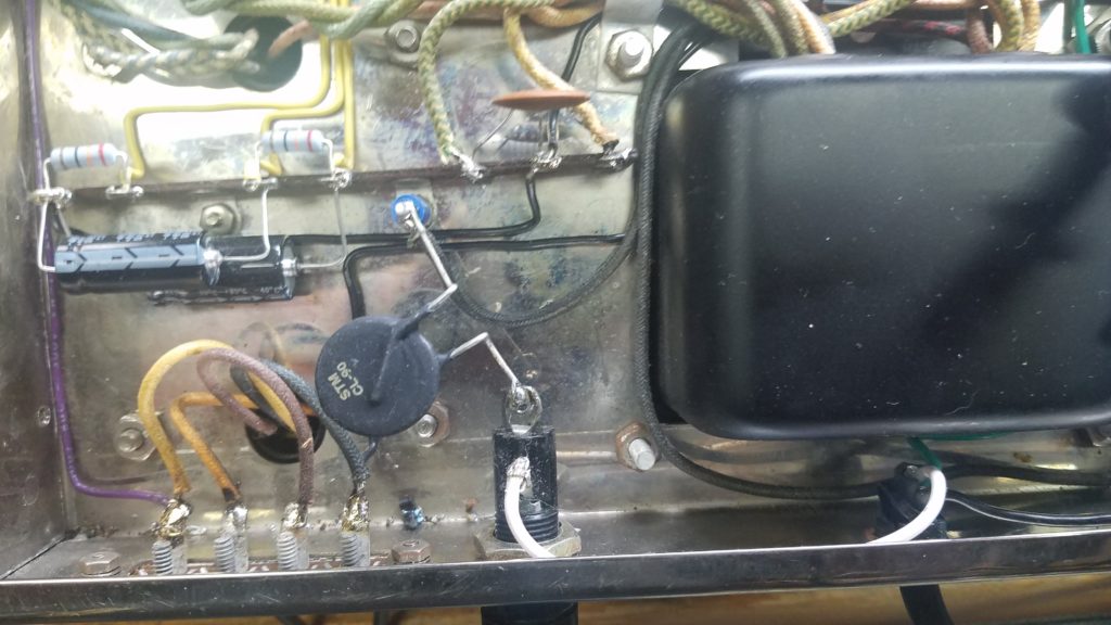
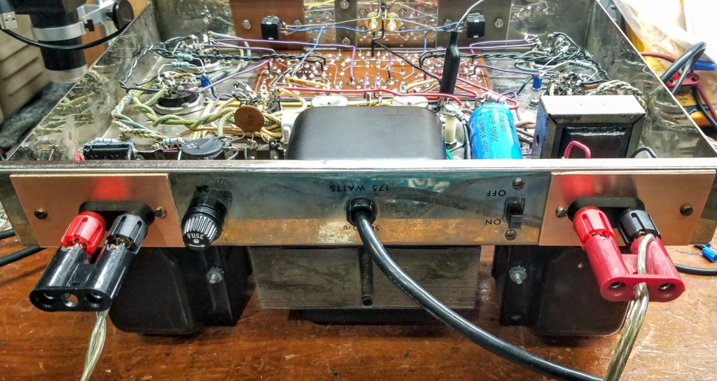
Done! Here’s the amp with proper safety, signal, and power supply star grounds finished.
Also visible is the thermistor for the surge current limit experiment, just to the left of the power transformer.
3. POWER – “Yellow sheet Mod”
1N4007 diodes in series with 5AR4 – prevents arcing
This mod has a lot of confusion around it! Anecdotally, this “yellow sheet” mod has helped the lifespan of 5AR4s, so it’s worth trying to understanding it. The actual mod is to insert a couple of 1N4007 (1kV) silicon diodes in series with the tube rectifier. But the reason why has been a bit vague…
1) One theory is this somehow helps preserve your rectifier tube by dropping the B+ AC supply voltage. The science doesn’t support this, as the forward drop of a 1N4007 is about 1 Volt. That’s unlikely to make a difference in a circuit with 10% tolerances and 360 volts RMS.
2) Another theory is if the rectifier tube fails and shorts out, this will save your filter cap by keeping full wave AC away from it. Although more plausible, a properly sized fuse should react to this over-current condition quickly enough. And a sudden increase of 50V or so will likely exceed the capacitors voltage rating, causing them to go boom! anyways. That hardly seems productive…
3) The most plausible theory is it can reduce the chance of the tube rectifier arcing over, a catastrophic event that will destroy the tube in very short order.
To step back a bit, rectifier arcing in a good tube is almost always caused by an over current condition.
3.A) One way arc-over can happen is too much first stage B+ capacitance, which causes a severe overcurrent condition.
The 5AR4 is spec’d for 60uF max (a 40uF can with the usual 50% tolerance), but I often see 80uF or more.
Don’t do this! The surge current to charge that big electrolytic filter cap will quickly destroy the rectifier tube!
Instead, add the extra capacitance *after* the choke, where it will do some good and the surge current won’t over stress the rectifier tube. This is the correct can capacitor to use: https://www.tubesandmore.com/products/capacitor-ce-mfg-525v-80403020-f
(Make sure the 40uF is the first stage and the 80 is the second just after the choke.)
3.B) Another way overcurrent can happen is with an old leaky filter cap. Basically, when this happens it draws too much current and gets hot enough to explode. The resultant foul smelling gunk is a real mess to clean up!
(BTW, the 1N4007 diodes won’t help or fix either of these filter cap problems.)
3.C) Another possible cause of an arc-over event is by exceeding the PIV (Peak Inverse Voltage) rating of the rectifier. A hot restart, like what a power glitch might force, can come close to this case. A hot start could allow the DC voltage on the filter capacitor (which hasn’t yet discharged) and the negative AC wave pattern from the power transformer to coincide, which together might exceed the PIV rating of the tube rectifiers.
Let’s look at this more closely.
Old stock Mullard 5AR4S are rated for 1700 PIV.
The PA60 B+ winding is spec’d 720 volts (360-0-360) AC RMS for a 117 volt input.
The one I just measured puts out 740 volts at 120 VAC in, so let’s call it 750 volt AC RMS.
So… That’s about 1040 VAC PP, then add in the 525V DC from the filter cap max, and we’re at 1565V PP. That would seem to be an acceptable margin (almost 10%).
UPDATE:
However, it appears the new run 5AR4’s are way less forgiving about PIV than NOS tubes. The spec sheets I found for the reissue JJ and Telefunkens say they are rated at only 1500V PIV, 200 volts less than the originals.
Ding, ding! We seem to have found the issue!
Anecdotally, it seems the reissue Tung Sols are indeed prone to arcing, per some videos I’ve found, like this one: https://www.youtube.com/watch?v=0AmIL__12V4Z
With that in hand, let’s look at this mod to see if there are any readily discernible downsides
UPDATE 1: 20121.01.14 – My high voltage (1.5 KV) scope probe came in. After checking it for accuracy and a quick alignment, It’s now time for some B+ research!
Here’s what the B+ rectified output of the 5AR4 looks like (into a 40 uF capacitor).
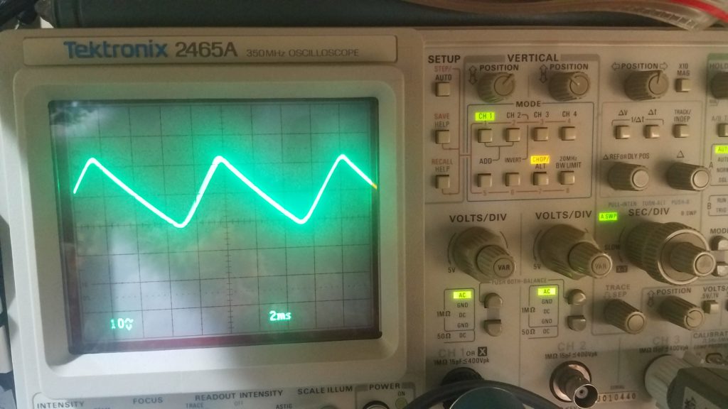
This is a typical and normal waveshape here. The ramps are caused by the filter capacitor charging and discharging, so all looks good.
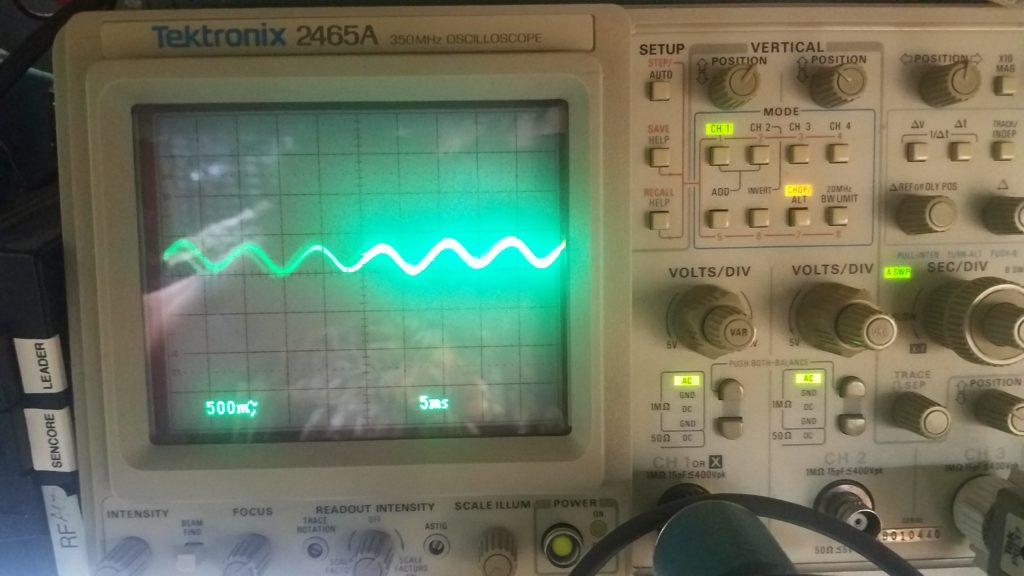
And post choke with 60uF of filtering, the B+ now looks like:
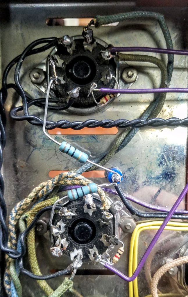
Next I’ll solder in the 1N4007 diodes using a pair of unused pins as terminals, like this:
(Schematic goes here)
After installation, the B+ voltages and ripple are the same.
And a quick analysis with my AP shows the amplifiers frequency response, THD, and the audio range FFT spectrum harmonics all look the same too.
Summary: This mod appears to not introduce any undesirable side effects.
I can not personally speak to whether it actually solves the arc over issue, but there are numerous reports on line that says it does. Seems like a good safety measure though, based on the numbers I examined.
– I recommend this mod, along with the following thermistor mod, and a latching off GFCI unit for best protection and safety for your ST-70 amp.
4. POWER
Thermistor add-on – why?
A) One theory is that it drops some ac line voltage, so your amp runs cooler.
…
However, it’s only a couple volts after warm-up (measured @2.8V @ 100C), less than standard line variances. With the appx 1:6 change through the xformer B+ windings, this theoretically amounts to about 16 volts RMS less to the B+ rectifier
I don’t see this as much of a factor, although it can’t hurt.
B) The generally accepted theory is it will minimize the inrush (i.e. turn-on surge) current.
…
This makes a lot of sense, even in amps that use a slow start rectifier like the 5AR4/GZ-34. Although the B+ comes up slowly, there is still a large current spike (caused by the filaments heating up) that might affect other equipment.
This article explains this all pretty well: https://peavey.com/PDFs/HPW-Chapter-6.pdf
Note that later Hafler solid state high power amp designs incorporate thermistors as part of the standard design; take a look at the DH500 schematic.
I’ll be looking at implementing a “soft-start” using a CL-90 thermistor, a readily available 120 ohm, 2 amp unit. Here’s the video clip I did on this:
https://daev.smugmug.com/2021/Web-clips/Dynaco-ST-70-clips/n-LqS77n/i-zsvDGRP
Summary: The thermistor indeed appears to reduces the inrush surge current and affords a soft start.
However:
-It takes a few minutes for the thermistor to “reset”, ie cool off; in that time the device will offer *no* surge protection during a high risk time. I’d pair this mod with a plug in GFCI adaptor that has the side effect of latching off in a power interruption along with the ground fault safety aspects. I use this one, which may be found on Amazon: Outlet-Adapter
-The heat the thermistor generates in operation (100C after a couple minutes) is a bit concerning for under the chassis work. I’ll need to do some temperature measuring to see if it is acceptable. UPDATE: Preliminary testing suggest this is not an issue, but I will monitor over a longer period to be sure.
More tinkering is in order here.
UPDATE 1: 2020.01.14
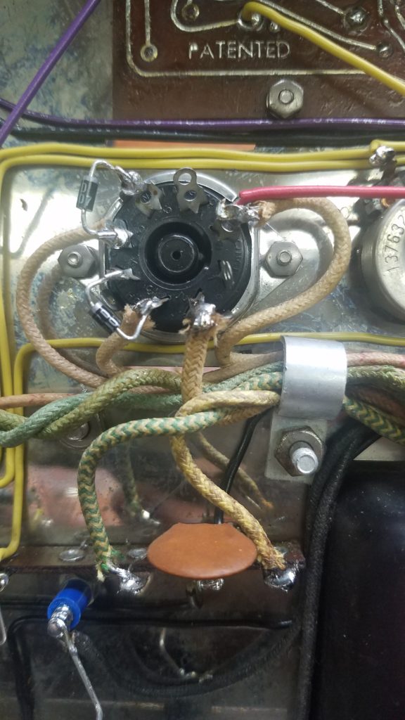
The best mounting location identified and thermistor installed. Note the clear air space around it; also note the mechanically secure turret at the other lead end.
(Never leave component leads flapping around in the air: it’s an accident waiting to happen. That goes double for AC lines!)
Note: There should be insulation “spaghetti” on the thermistor leads for safety, I’ll put that on once I’m done prototyping and update this photo.
My inrush meter arrived, a Mastech MS2108 meter and a 10X inline current loop. I haven’t verified it’s accuracy yet, I just plugged it in to see what it says.
– Without the thermistor, I measured a 5 amp inrush at 117 volts, and the amps steady state draw is about 1.5 amps. (The former is believable based on the analog AC meter kick, the latter agrees with the AC analog ammeter once it settles.)
– With thermistor in circuit: not enough surge to trip the meter.
These results are about what I would expect, and helps explains why the ST70 and PAT power switches goes bad so often. (The ST70 switch is only rated for 3 amps AC, I assume the PAT uses the same switch.)
Also, the power switch doesn’t have the now standard 0.01 uF @1KV snubber capacitor across the contacts, another new checklist item.
Here’s a quick schematic sketch of the revised AC line side of the power transformer. Note the snubber cap, the grounded AC cord, and the thermistor are all new adds.
UPDATE 2: 2020.01.20
The thermistor should permit the use of a 2.5 amp fast blow fuse for even better amp protection. I’ve put one in while I finish working on this unit to see how it goes.
So far so good.
Technically, the AC black (hot) wire should have the fuse in it, but the kit was designed before that standard and was the “wrong” way, and the existing wiring isn’t long enough to change it.
Summary:
This mod appears to not introduce any undesirable side effects in performance, although I still need to look at the possible temperature issue.
– I recommend replacing the power cord with a grounded one, this mod, a latching off GFCI, and the previous power rectifier diode mod for best safety and protection for your amp.
5. 7199 driver replacements: 6U8A/6GH8A
This one is controversial, lots of opinions here.
Background:
The 7199 appears to have been designed by RCA in the late 50’s, or at least they put out the only ap-note I’ve seen, AN-183. According to this note, the 7199 Triode-pentode was targeted squarely at the audio industry. It was designed for low noise & hum, resistance to microphonics, and high gain.
In theory, it was perfect for the typical amps front end gain-and-phase-splitter A/B amp design. It was used in HH Scott, Heathkit, and of course Dynaco hifi amps, among others.
A) Unfortunately, the 7199 is apparently a rather difficult tube to manufacture correctly.
*If* you can get good NOS 7199’s, they can work well. Unfortunately, these good NOS version ceased being manufactured in the 70’s, best guess. Now, 50 years later, they tend to be very inconsistent in terms of frequency response, noise, and reliability.
B) The “modern” reissue from Sovtek always had serious quality control issues and Sovtek likewise ceased manufacturing them again around 2007. On top of the previous issues mentioned, the Sovtek reruns had very short lifespans, occasionally measured in minutes. 🙁
C) In spite of the stated design goal, many 7199’s are strongly microphonic, a very annoying failure mode.
D) When 6U8A/6GH8A’s are used with adaptor sockets, you don’t even have to rewire sockets. And a bonus, it gets this hot tube away from the fragile OEM dyna driver board so it doesn’t get scorched, an unfortunately common problem.
E) NOS 6U8A/6GH8A’s are very consistent, are rugged, and readily available. (Note: the 6GH8A is slightly higher gain, similar to the 7199.)
When measured on an Audio Precision analyzer, these tubes will meet meet or exceed factory specs for the stereo 70 .
Summary: Unless you can grade your 7199’s for quality in the amp, 6GH8’s (or 6U8As) are a fine alternate choice, at least in Dynaco 70’s. And the tall cage size means you can use the adaptor sockets instead of rewiring your amp.
Other amps may yield different results, of course.
I’ll post THD vs frequency, power bandwidth, and IM distortion charts someday…
6. Use low wattage “fuse” resistor on each output tubes cathode for precise current balancing
I highly recommend replacing the pair of now whacky & probably out of tolerance 15.6 ohm resistors with four precision 10.0 ohm, low wattage (1/4 to 1/2 watt is good) resistors, one for each of the four output tubes cathodes.
This has multiple benefits:
1) You can precisely monitor each output tubes current easily and safely.
2) You can see if your “matched pair” is still matched, and when they start drifting into mismatch land.
3) A severe over-current condition (bias supply failure, output tube short, bad socket connection, etc.) will simply burn out the resistor like a fuse, protecting your priceless transformers and expensive output tubes. And the burned resistor will tell you which tube had issues. (Also, see the section for adding separate bias controls; this is a prerequisite.)
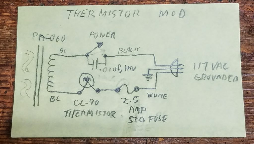
Here’s a pic of the halfway point on the conversion. The single 15.6 ohm resistor and the jumper between the tubes cathodes has been removed, and the two new 10.0 ohm resistors are attached to each socket pins 8 and 1.
The leads are dressed to go over to a forthcoming turret standoff mounted in the cooling slot, not the ground tab on the socket. This is crucial as I am also implementing a proper safety ground and a star signal grounding schema in this unit. (See grounds on this page.)
Also notice the resistors are dressed for easy access. This is to give you plenty of space to clip a DVM for measuring the voltage drop across them. Via the science of Ohms law, you can precisely calculate the idle current for each of your precious output tubes.
eg 10.0 ohms with 0.45 Volts across it is 0.045 amps,
or, in more accessible terms: 450 mV across 10.0 ohms means 45 mA.
(convenient, no?)
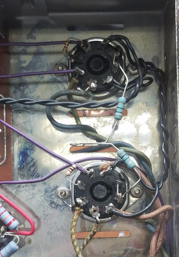
And here’s the finished mod (on the other channel).
How to use this mod properly
- When it’s time to check the idle current (i.e. bias) about once a year, or anytime a tube or part is changed, remember to carefully zero out your meter and test leads before measuring the cathode resistor’s current value.
- Jot down the precise resistance values. Even if they start out precisely at 10.0 ohms, some drift will occur over time.
- Fire up the amp and let it warm up fully, about 30 minutes.
- Measure the DC drop across each resistor, then divide that voltage drop by the resistance. eg 10.0 ohms with 0.450 Volts is 0.045 amps,
or, in more accessible terms, 450 mV across 10.0 ohms means 45 mA of idle current.
Voila! You now know the cathode current for each output tube. - If you’re a cautious type like me, let the amp play music for a few hours, then check resistances and voltage drops again. They might need a bit of touch up due to thermal drift, but it shouldn’t be much.
- Note: The original 50 mA per tube spec is pretty close to the maximums for a well constructed NOS EL34, like the original high quality Mullards, not to mention the B+ rectifier tube! Current production tubes aren’t quite as rugged, so I recommend running them 10% to 20% cooler (40-45 mA) to preserve their life. And if you’re fortunate to have some nice vintage Mullard outputs, running them a bit cooler will greatly increase their lifespan too.
7. Bias control for each tube
Along with the previous cathode resistor mod this mod permits plate current balancing (basic current “matching” of the output tubes), which is a good starting point for optimal tube life and performance. There’s two ways to do this, either a separate control for each tube, or adding a DC balance trimmer to the “master” pot that’s already there. I’ve done both ways on other amps, depending on physical space and what’s already there.
I haven’t decided what I’ll do here yet, contemplating.
I’ll probably go for a trimmer per output tube under chassis.
UPDATE 1: Decided to swap out the driver board for a more modern driver board design. from http://www.tubes4hifi.com/ST70.htm It has 4 trimmers, one per tube on it, so done!
8. Adding an input level control
One of my favorite mods, this allows you to precisely trim the two amp sides to have the same gain, something they rarely accomplish on their own. It is also useful for swapping input cables without powering off the amp, like when you inevitably get Left and Right reversed. 🙂
Also, this is needed for the next trick, running in true bridged mode.
I just pull the PTO sockets and wiring, fill the big ugly socket hole with a copper or brass plate, and then mount the pot in the plate.
Note: Keep the PTO sockets, they make good spares for worn output tube or rectifier sockets.
I use 100K, log taper pots here as I drive my units with a SS preamp and this will slightly reduce the noise floor. If you plan on using a tube preamp without a cathode follower (like the PAS series), for your preamp, then use a 500K pot to prevent loading down the preamp and rolling off your bass response.
Pro tip: Add a pair of large knobs and it looks factory! I happened to have a pair of vintage Dyna knobs here.
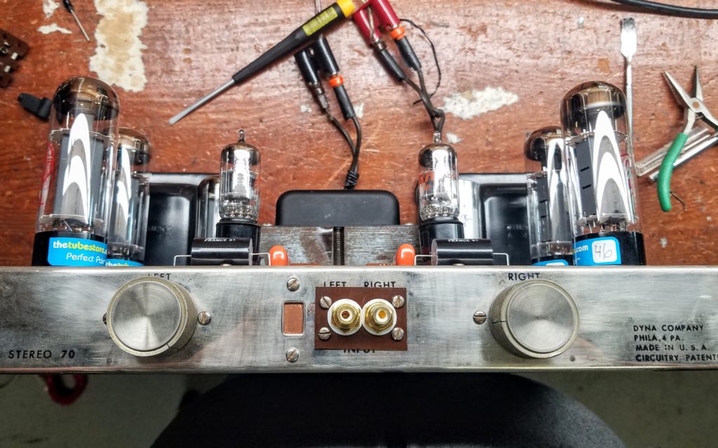
First input change; better quality and better spaced RCA/cinch jacks.
9. Running a ST-70 amp in true bridged mode
Fun fact: You can easily get more power (around 3dBW more) if you run a 2 channel amp as a single mono amp in a bridged “push-pull” config. This is not the goofy parallel mode the amp came with, this is legit double the power.
The advantages are:
– Doubles the output power to appx 70 watts. Can be more than double depending on amp design and power supply constraints.
– Quieter. The in phase power supply 120Hz buzz tends to null out.
The down sides are:
– You will need two stereo amps for 2 channels.
– The amp channels need to be closely matched in gain and freq response, not always the case with old tube amps.
– Theoretically halves the already poor damping factor of 9, meaning the Dyna’s bass will get even flabbier. I suggest an active crossover at 85 Hz or so and a good sub, see here:
– You must invert the phase of one of the channels. (That’s 180 degrees out of phase if you’re following along at home.)
Rather than the hassle of building a clean phase inverter for one amp, we can cheat by simply driving the two sides with a balanced signal, which give us the signals we need for free.
To play with this, hook a 8 ohm speaker across the 4 ohm taps and then drive the inputs with a balanced “pro level” signal. (I use an adaptor cable with male RCA’s and a female XLR connector.) Volume trims (not included on the original dyna design, but a favorite mod of mine) will let you exactly balance the gains for this trick.
I’m doing this for my center channel amp in my home theater setup, it sounds great. Whether it’s twice as good is unknowable, 🙂
10. Running a ST70 in “triode” mode (half the power)
A long held belief is that a triode output topology is more magical musically. There are persuasive arguments “fer and agin”, why not try it and see what you think?
I’ll likely be installing an under chassis switch and running some measurements, as well as listening.
11. TECH Changing the ST70 feedback loops and/or the low pass filter
Possibilities include using the 8 ohm tap, and/or fine tuning the values for best square wave shape with the least ringing.
12. Signal path capacitor changes
- Driver to output tube couplers – Increasing to 1.0 uF – well known change.
- Input tube grid capacitor – Increasing this to a 0.10 uF flattens the low frequency response and lowers distortion a bit more, assuming the prior change was done.
13. SIGNAL
Installing dual banana speaker output terminals
I’ve never liked the screw terminal approach for speakers outputs. They’re too clunky and annoying when hooking up speakers, and it’s far too easy for a stray wire to wander and short out the connection.
I prefer dual banana plug binding posts, where one simple plug (which can be quickly flipped for speaker polarity checking) is easily connected and disconnected. The good ones can handle 15 amps, the cheapies about 5. This terminal type also allows large spade lugs (and bare wire when needed) to be used.
However, most Dyna terminal post retrofits have one or more of these problems:
A) They lose the ability to select the impedance you want without soldering.
B) They leave an ugly chassis hole exposed (something I dislike)
C) They aren’t spaced for a dual banana plug (something that really annoys me)
D) They require new holes in the chassis (something I strive to avoid)
This simple mode takes care of all those problems
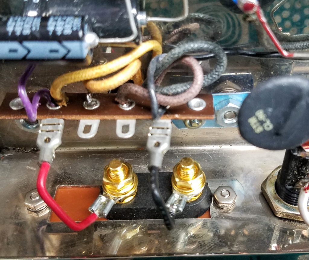
First, I piggy-backed a 4 position terminal strip onto the output transformers mounting screws, and carefully moved the speaker output tap wires there. By soldering to the lower eyelet, the upper part can be used as the “tang” for a push-on terminal, which allows for easy impedance selection. As usual, avoid clipping the transformer leads shorter; coil them neatly instead.
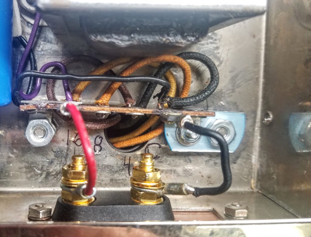
The dual banana jack is mounted on an old piece of copper clad PCB. It neatly covers the ugly square hole left by the terminal strip and maintains the chassis electrostatic ground surface.
Here’s the finished terminal mod:
Also note grounded power cord,
Here’s a closeup of the terminal strip for selecting the impedance.
And now you’re asking why I didn’t center the dual banana jacks, right? 🙂
There are two other mods I’m contemplating: moving the input jacks and a Triode/Ultralinear switch, and perhaps one of those will go next to the bananas. Hopefully the RCA’s will fit.
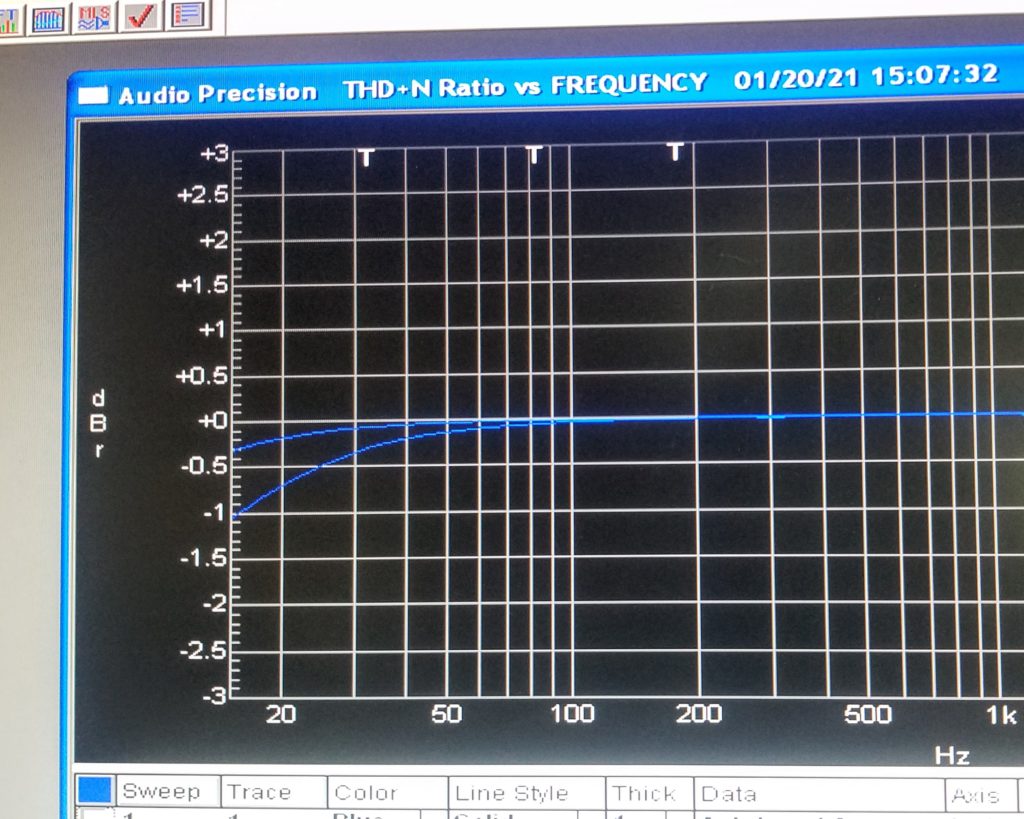
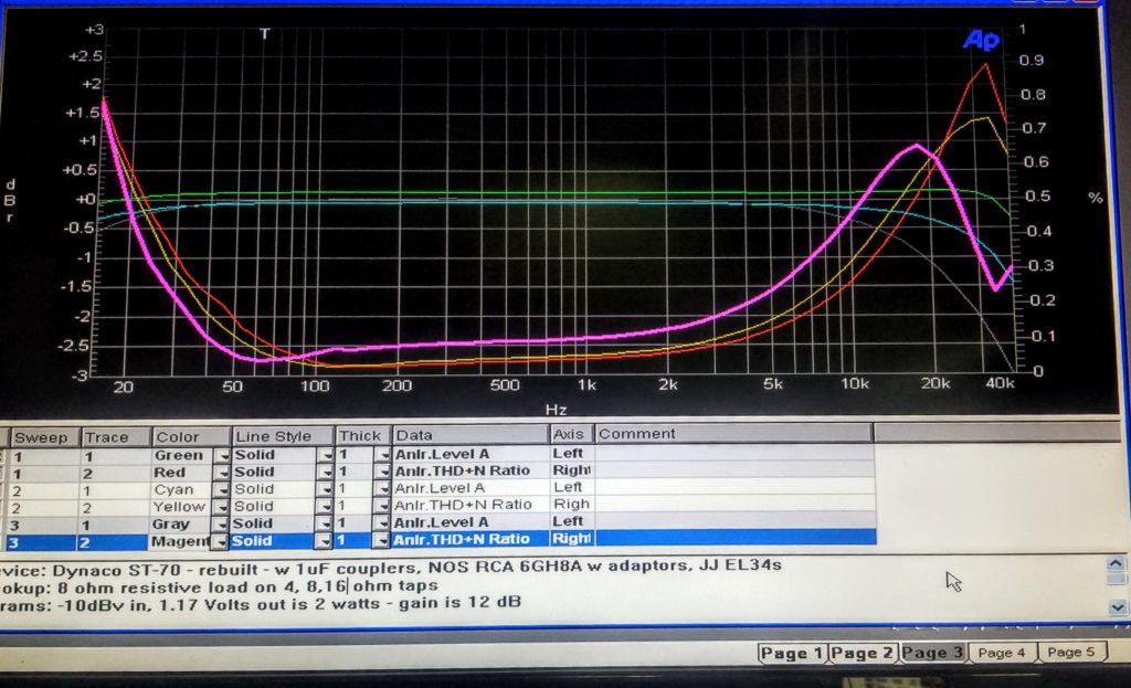
Oh, speaking of output taps… here’s an interesting plot:
This is a Frequency vs THD plot into an 8 ohm resistive load, scale +/-3dB and 0 to 1% THD.
The three graph pairs are:
4 ohm – Green/Red
8 ohm – Cyan/Yellow
16 ohm – Grey/Magenta
14. SIGNAL
Moving the RCA/Phono/Cinch input jacks to the back of the chassis
Having the input jacks on the front panel is really too retro.
It is also annoyingly ugly.
However, the short signal path is a good idea. I’ll experiment with moving the jacks to the back, which means I need to carefully measure the noise floor and spectrum before and after.
15. UPGRADE
VTA-ST70 driver board
Too much for here inline: See VTA ST-70 CCS upgrade
Vendor page: VTA-70 PCB http://www.tubes4hifi.com/ST70.htm
16. POWER
Replacing the 5AR4 tube w a SS rectifier
There’s a lot to consider here: Reliability, resale value, performance, cost, etc.
My take is “do no harm, i.e. if you do this, also do the thermistor current limiter mod and build your “replacement” on a tube socket so a later someone can swap the 5AR4 back in if desired.
I whipped up my SS rectifier on a tube socket as a plugin module, with two 1000 PIV diodes and a 50 ohm, 10 watt series dropping resistor to approximate the 5AR4 voltage drop.
Looks like: (INSERT PIC)
Bad Mods and Myths
- Bad mod: Filter cap too big
Put a huge capacitor on the rectifier, more is better, right?
No, do not place more than 40uF of B+ filtering on the first stage of a 5AR4’s filter circuit! The 5AR4 rectifier can’t handle more than about 60uF absolute max (this is a 40 uF can with the usual 50% tolerance factored in) due to the surge currents involved. Exceeding this rating will severely stress the rectifier tube leading to premature failure.
That said, it is both safe and a good idea to put more filtering in the *second stage*, after the choke (which also buffers the surge current).
- Bad mod: Regulate bias voltage
Bias is important to get perfect, so why not regulate the negative bias supply on a St-70?
No, don’t do this! In these units, the implementation is both simple and very clever. As the AC line voltages changes, the unregulated bias supply changes proportionately; i.e. it tracks the line voltage. This helps prevent a dangerous over current condition when the AC line voltage is on the high side. - Also note the bias voltage setting isn’t as fussy as people think.
Here’s a “before first power on” checklist:
- Carefully inspect the AC line cord, replace if it’s cracked or damaged.
Ditto for the rubber grommet. (I recommend upgrading to a three wire grounded cable with a crimping strain relief grommet for safety, see below.) - Check the fuse, make sure it’s the correct rating and type (eg slow blow vs fast). It’s common for older amps to start drawing more current as the parts age, and some owners just stuck in larger fuses rather then get the amp serviced. (!)
- Inspect the chassis and PCB wiring, any scorch marks means there was a prior issue to be dealt with. Don’t power up until you figure this out.
- Pull and test the tubes. With tubes pulled, check the various resistors haven’t drifted and replace any that are now out of tolerance.
I usually just replace all the plate resistors a this point. Heat makes the old carbon comps change value, and they tend to get noisy from age and moisture.
Additional for power amps – more unit safety
Key point: If the output tubes bias voltage goes too low ( not enough negative voltage) , the output circuit current will exceed ratings. Then your tubes will burn out, and possibly the output transformer as well. 🙁
(This is an undesirable outcome, in case it’s not obvious…) - Refurb the bias power supply. Replace the failure prone selenium rectifier with a silicon one and install new filtering caps. The first dropping resistor usually needs to be increased to about 18K, as the new rectifier is more efficient. Remember this is a negative supply, so the new diode and filter caps are backwards with respect to ground.
- Replace the driver-to-output stage coupler caps. That means 4 of them in the ST-70. Those old black cats (or bumblebee’s) are almost always leaky by now, and will cause the output bias voltage to drift downwards. BTW, the original 0.1uF caps are undersized and roll off the bass too much, I recommend replacing with 1 uF. Personally, I like use 1uF 600 V Solens caps here, they fit neatly in the space provided.
First power up – looking for problems and reforming the B+ filter caps.
Pull all the tubes.
Temporarily replace the 5AR4 tube with a SS replacement, and put voltmeters on the B+ and bias supplies. Also put an AC ammeter on the AC line input.
Using a variac, apply about 20 VAC to the mains, check for appx 1/6th voltages and no hot caps or burning smells. If all seems well, let it sit for a few hours while monitoring it.
(The idea here is to safely reform the filter capacitors enough to test out the unit.)
If everything looks good and the current looks normal run the variac up to 40 volts, repeat the couple of hours conditioning process, then 60, then 80.
If the voltages all track and the AC line current stayed low, you can try the amp with the tubes in place. (You already checked the fuse, replaced the couplers and rebuilt the bias supply, of course, right?)
This time hook up speakers and a signal generator. Again, go up slowly, around 60-80 VAC until you start to hear audio; stop there. (It may may be distorted yet, that’s OK.) Check bias the voltage is roughly proportionate, ie 60 VAC line should also be about half the bias voltage (and current, via ohm law). Let it bake a hour or so, keeping an ear on the audio. If it cuts out or makes weird noises, turn off power and find the problem. “Spitting” or “popping” noises are usually the plate resistors, I replace them with the couplers as a matter of course. Loud bangs, squealing, or intermittents are harder to track down without lab equipment, like a ‘scope.
If it everything still looks OK, run up to 90 VAC and again check voltages and AC line current, let it bake awhile. The audio should be pretty clean now.
(more to come here)
Common myths and misconceptions
“Modern AC line voltage is too high for these units, they were designed for 110 VAC.”
Mostly false, look at the schematic.
The ST-70 clearly states the design line voltage is 117 VAC, and the text on the same page refers to 120 VAC. When you factor in the typical voltage tolerances of of 10%, unless your AC line is way over spec these units will be fine.
That said, a slightly lower line voltage (like 110V) will reduce stress on these 50+ yr old units and is not a bad idea for longevity.
“Model 70’s have great bass.”
This one might be controversial. Lots of folks love the bass of their 70’s!
Still, this one really puzzles me, for these reasons:
– The low end in a typical unmodified ST-70 starts rolling off at about 80Hz, and the THD starts rising rapidly, generating spurious harmonic distortion. This also means the power bandwidth is quite constrained. Even increasing the coupling caps to 1 uF (10x their factory size) only pushes the full power low end down a bit to 50Hz or so, as seen below. (This is still a recommended change, as it cleans up the feedback loop quite a bit.)
– The damping factor (how well an amp controls back EMF from the speaker) is quite low. It is spec’d at 15, reviewers have measured it more like 9, which is what I’ve measured too. (A low cost SS amp easily hits 5 to 10 times that.) The audibility of a low damping factor is nicely set out in this article by Dick Pierce: https://www.audioholics.com/audio-amplifier/damping-factor-effects-on-system-response
– The B+ power supply is a fairly soft, so those power hungry bass notes will cause the voltage to sag, which in turn modulates the rest of the frequency spectrum being amplified. To me, it sounds like a bit like wow on a turntable.
Here’s an actual frequence vs THD measurement taken at two watts on one of my refurbed ST-70’s. This one is using a refurbed “stock” driver board, with 1 uF couplers, 0.1 grid capacitors, and another 40 uF on the second stage filter as the only performance mods. The larger capacitors flatten the low end response down to about 20Hz with rapidly rising distortion at around 50Hz.
The THD scale is from 0 to 1% with 0.5% in the middle, red/yellow/cyan lines.
The Frequency response scale is +/-3dBR, with 0 in the middle, blue/green lines.
This all contributes to a flabby and harmonically rich deep bass on these units. On first or casual listening it might sound pleasant, but careful listening to deep bass percusive instruments (like kettle drums, pipe organs, or guitar string plucks) will illuminate the issue.
Do yourself a solid, try this instead.
Pick up a decent sub (and an active line level crossover if the sub doesn’t have one).
As a starting point, send everything below 85 hertz (low pass) to your sub and everything else (high pass) to your Model 70. Adjust the sub to blend and match your main speakers. Once dialed in, your system will sound much cleaner (and louder, if that’s your thing). The bass will be much tighter and have better punch, and that magical sweet tube midrange will be all the more apparent.
LINKS TO OTHER INTERESTING BITS OF DATA:
https://audiokarma.org/forums/index.php?threads/dynaco-st-70-base-line-testing.578485/
Ed notes:
Investigate using the 5 volt winding as a bucking winding when using a SS rectifier.