Last Updated on 2026-06-15 by Daev Roehr
(incept date: 2025.10.15)
I’ve wanted to do two 901 “adjacent” things for a while:
1) Compare the early series sealed box 901 EQ curve with the later ported series curve. General consensus is the low frequency roll-off is sharper in the later “ported” series, but are there any other significant differences?
2) Perform a “before and after” EQ restoration comparison, i.e. quantify the differences between an original untouched processor, and then after refurbing it as needed.
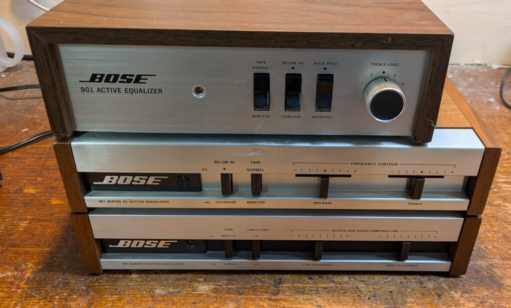
To do all that, I need samples. Working samples, that is. I’ve been keeping an eye out, and when one pops up (at a fair price), I attempt to acquire it. So far, I’ve obtained these four: 901 EQ’s: Series II, III, IV, and a series VI (in use, not shown) .
I’m still on the lookout for the Series I, V, IV.B(a backported V), and VI version 2.
( But I’m not made of money either, so I wait for the bargains. 🙂 )
Series II-IV-VI comparisons: the tl;dr version
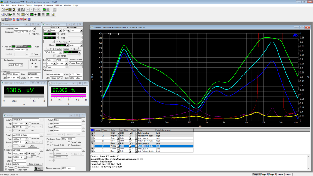
The initial samples used were a Series II, a Series IV , and a Series VI as representatives. After confirming my 901 EQ samples currently meet factory specs (best guess against service notes, confirmed by L/R channel matching), I measured them all on my ancient but still trustworthy Audio Precision One audio analyzer.
All controls were centered or in “default” positions.
The stimulus signal reference level is consumer, -10 dBV@400 Hz.
The frequency sweep is 40KHz down to 15 Hz.
I put them all on the same graph with the same test conditions and stimuli.
The graph amplitude scale on the left is -12 to +24 dBR.
The THD at each frequency test point is also measured, and the scale is 0 to 1%, labeled on the right.
Series II is Blue/Red, Series IV is Green/Yellow, and Series VI is Cyan/Magenta, with the first color being frequency, the second THD.
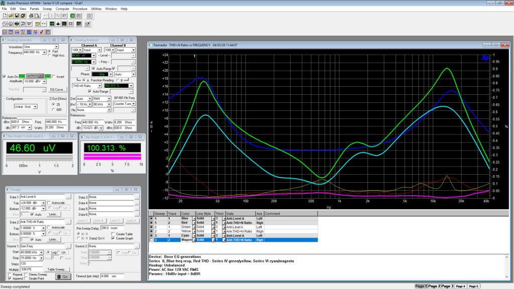
The noise floor of the II was about 250 uV, the IV 150 uV, and the VI about 50 uV.
Question 1 answer:
A) Yes, the generational change eq curves are quite different.
Notably, using a series I or II eq on the later series speakers is not a good idea. The larger bass boost would make it far too easy to bottom out the ported box drivers, even at moderate volumes, and rumble would likely be a problem as well.
B) It is generally a bad idea to use *any* of the 901 eq’s on regular speakers. The large bass boost will be too much for many woofers, and the huge treble boost could easily fry tweeters. Not to mention ears.
Now, back to our story…
Series II
I recently came across a 901 series II EQ in unknown “unworking” condition for cheap, so I picked it up to scratch that curiosity itch. Also, I’ll have the correct eq laying about should I encounter a screamin’ deal on a series II pair.
Electronically, these devices are easy to work on and the schematic (with voltages) is readily available. Piece of cake for a electronics hobbyist!
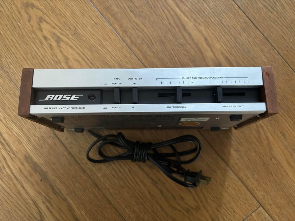
Front Panel view
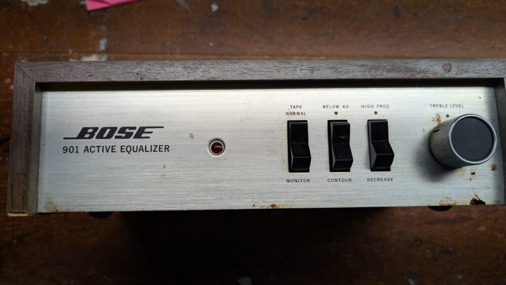
Front panel view, as it came. Dirty, but not badly scratched up. The wooden box has some chips and dings but it’s all mostly there. The panel has all the lettering still intact, and the knob looks correct too. I’ll glue the crumbly bits, carefully clean the vinyl, and re-stain where needed.
Cleaned front panel
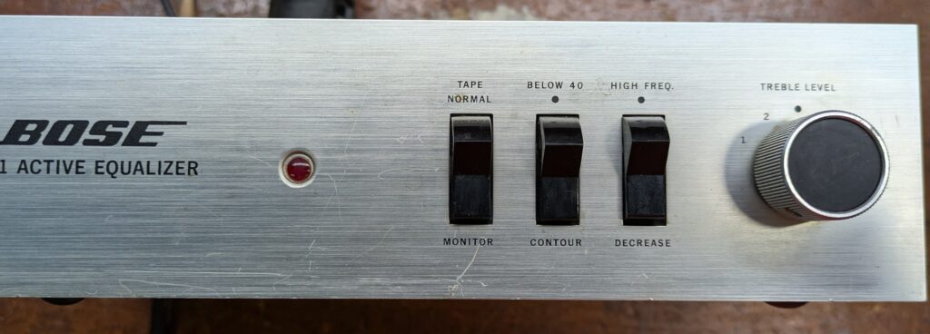
Front panel, after cleaning with water and Q-tip, then a little Flitz metal polish. One scratch is rather deep, but much better looking, good enough for now.
Inside the box
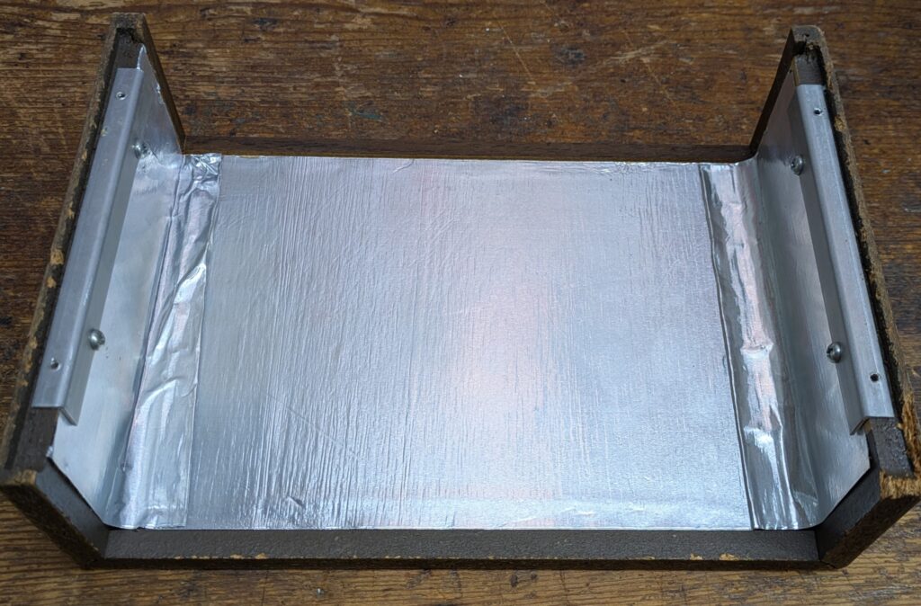
Check out the foil shielding inside the wooden box!
As a person that worked on many consumer products, this looks to me like a “whoopsie!” was found in testing and a quick shielding fix was implemented.
Later Bose EQ units went to a metal box, which bolsters this theory too.
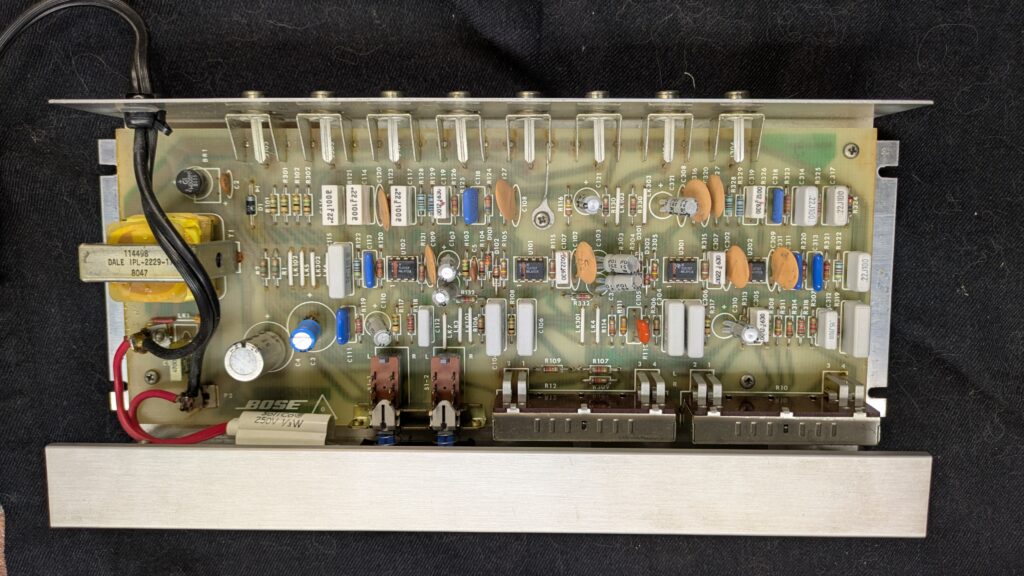
PCB view, first look
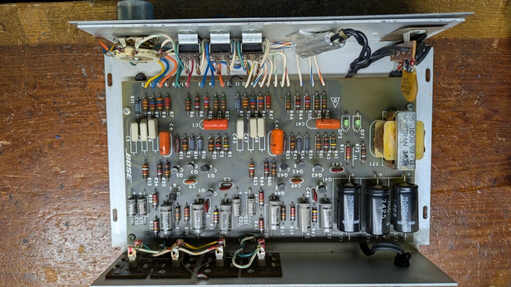
Looks clean and unmolested, no bulgy caps or burned resistors. It’s a straightforward design, using discrete parts and a single ended power supply.
It also has a neon power indicator, which are great little RFI noise sources.
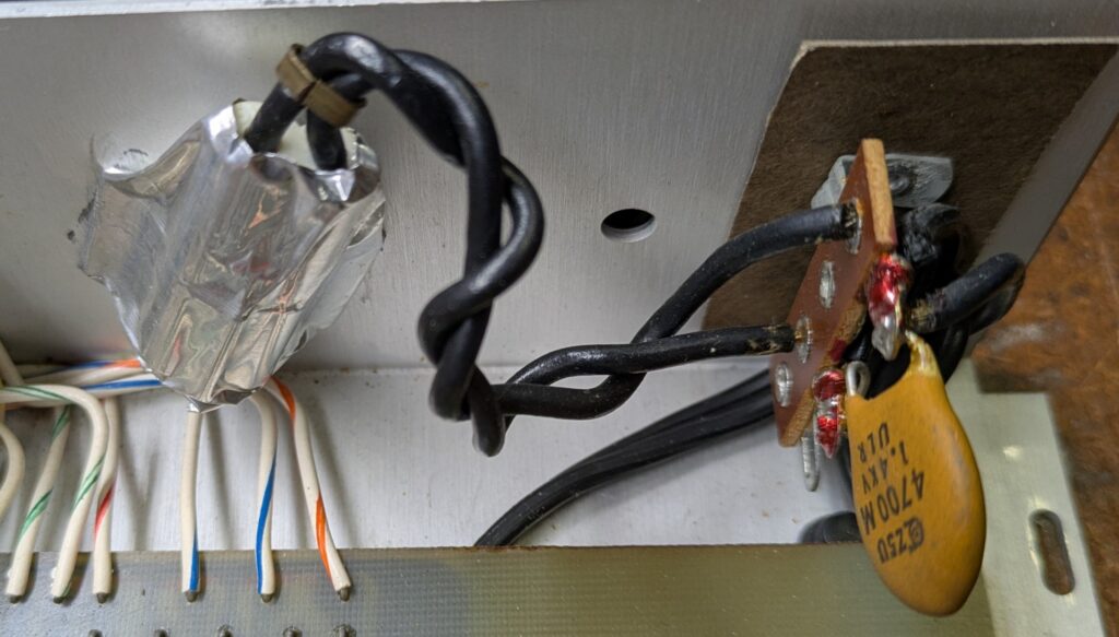
Yup, extra “kludged” shielding, twisted wires, and the line cap all suggest noise was an issue. Ick. Even if f the neon still works (unlikely), I’ll replace it to reduce the unit’s noise floor and clean up the AC wiring.
UPDATE: As expected, the neon is dead. The lens and housing easily disassembles…
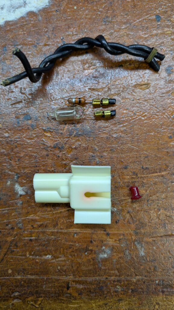
… so I’ll try rebuilding it with a junkbox red LED and 2K resistor inside, hooked up to the first filter stage. I think the power transformer will handle another 10 mA for a LED just fine.
UPDATE: Oops, the tiny red lens went skittering off my bench and into the vastness of my shop floor, never to be seen again. 🙁
On to Plan B, a larger LED and a turret to anchor it.
First power-up
First, I’ll do some safety checks for the AC side of things.
The unit is UL listed, but has no AC line fuse. That’s typical of a low power electronics device 50 years ago, but I’ll put an in-line fuse in because reasons. The plug doesn’t measure as a short (about 750 ohms, yay) so the AC side looks safe to power up.
But before I do, I’ll do a quick in-circuit ESR check of the power supply electrolytics.
Heat is a capacitors worst enemy, but nothing gets hot in this unit so they may be OK.
In-circuit, the original power supply caps have about 4 times the ESR they should be, not too bad. That means they may reform with a careful powerup, which leads to…
OK, time to power it up slowly on a variac to reduce the chances of a catastrophic failure.
I started at 20 VAC line for a half hour, then 40 VAC for an hour, then 60 for an hour. (These timings are somewhat arbitrary, and probably overly long. I just set the voltage and do other things for a while, in the “it works, don’t mess with it” mode. )
At 60 VAC, the dc supply at the first filter was 10 VDC, right on the nose, based on 20VDC at 120 VAC. The first filter cap showed the usual sawtooth of the filter cap doing it’s filter thing, ripple appx 170 mV PP looks about right.
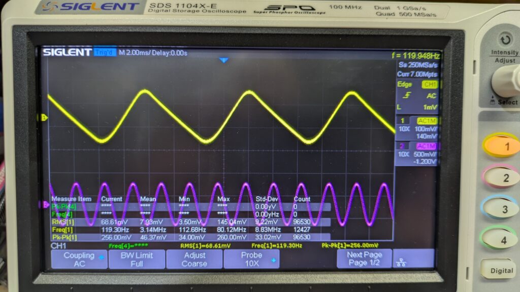
At 90 VAV, supply DC still on track at 15 VDC, and a sine wave sweep shows a clean signal, so onto 120 VAC and testing! Ripple at the first cap is down to 140 mV, probably due to my careful reforming being somewhat successful.
Audio testing
A first frequency and THD sweep at -10 dBv, controls at nominal (dot) positions.
THD is about 0.1% over most of the audio band. As there is no distortion spec in the service manual, I can’t say for sure if this meets spec or not. It *is* a bit high by today’s standards, but it’s also fairly typical of that era. I may experiment with lower noise transistors in the darlington gain spots. I also see the channel gain tracking is off by about 1 dB, that’s likely age related R/C component drift.
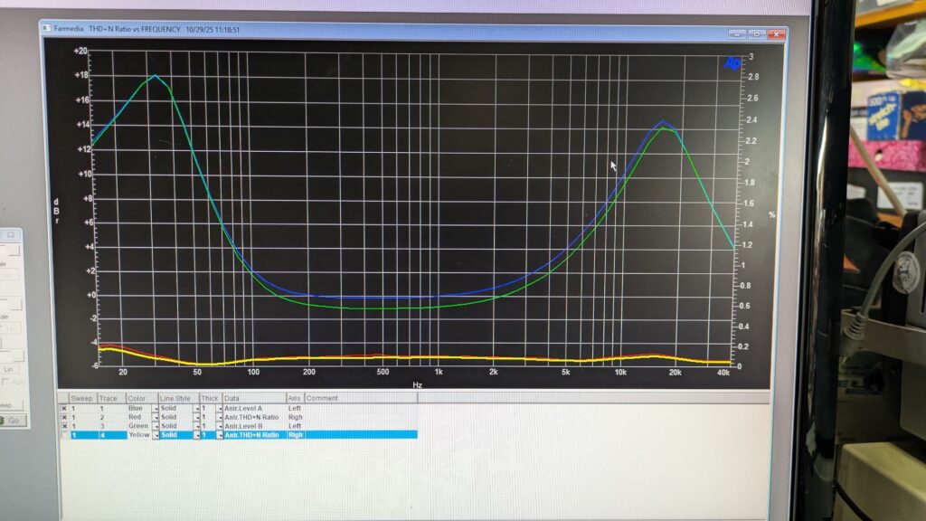
The EQ boosts (14 dB at 15 kHz and 18 dB at 35 Hz) are indeed massive!
If you were listening at just 1 watt average program, an pipe organ low C note (16′ pipe, 32 Hz) would need close to 100 watts to avoid clipping! No wonder big amps were specified.
I also see the eq curve is very different from the V/VI series eq. The flat “unity gain” portion of the curve is quite broad, from about 200 Hz to 2 kHz, and the series V/VI mid range tilt and notch compensation is absent.
A second sweep at 0 dBV (1 VRMS) shows a sharp increase in THD in the treble. It’s obviously clipping hard, not surprising with that huge boost and a 20 VDC rail. Keep the input levels at standard -10dBV consumer levels and things are good.
Next, I flipped the two rockers down to their “contour” and “decrease” settings…
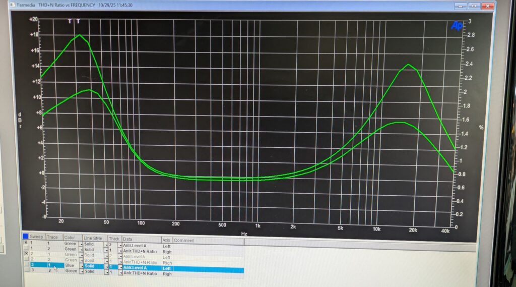
…and the boosts become much more moderate, about 7 dB less. Interestingly, the “standard setting” curve is not far off from the classic Fletcher-Munson loudness curve.
(I speculate the “standard” settings might be an early take at the “Bose House Sound”, perhaps?)
In any event, this less aggressive setting would actually make a decent loudness equalizer for standard speakers (heh, heh) and will greatly reduce the power requirements to achieve a given SPL.
Finally, here’s the rotary treble switch in all 5 positions.
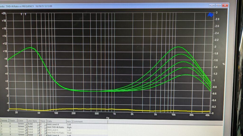
Each step is a 2dB difference, so the rotary switch changes the treble boost from a low of 4 to a high of 2 dB, appx.
If the dot at position 3 is assumed to be the “nominal” position, then it provides a useful amount of treble “boost” or “cut” for over damped or too bright rooms.
The noise floor was at 230 and 280 uV, left and right, cover off. Doesn’t have a noticeable hum component, mostly thermal noise.
OK, rebuild and cleanup done, as of 2025.12.02.
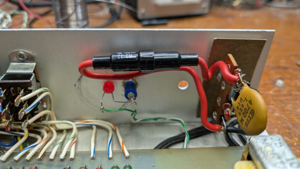
Fuse added, neon replaced with LED.
(A bit of a kludge, but it looks nice from the front.)
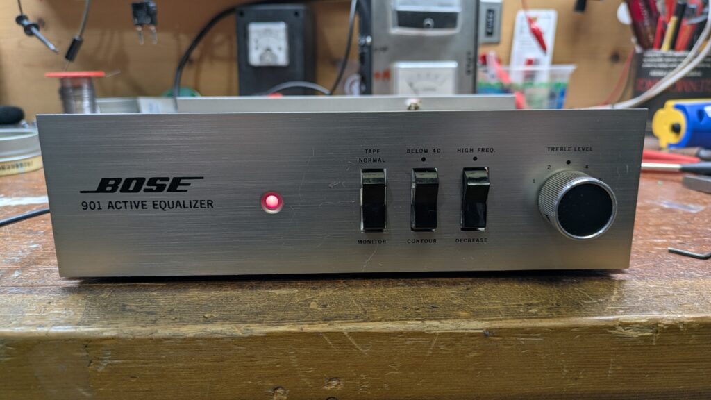
And the cleaned up panel and knob with the LED glowing.
SERIES III
Obtained a Series III in 2026, May. Condition unknown, in transit.
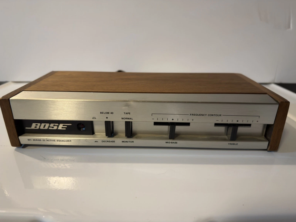
Image from eBay sale.
PCB image
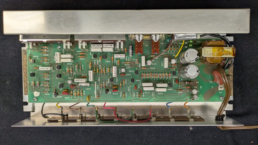
The design is still discrete transistor, and the 240 change is clearly labeled.
Series IV
Obtained a nice condition Series IV in 2026, March.
The IV is supposed to be the same eq curve, as the III.
I’ll know once I test them both.
Looks like some caps have been replaced, but they appear to be the correct values.
Series IV with op amp PCB, +/- 15 volt power rails, zener regulated
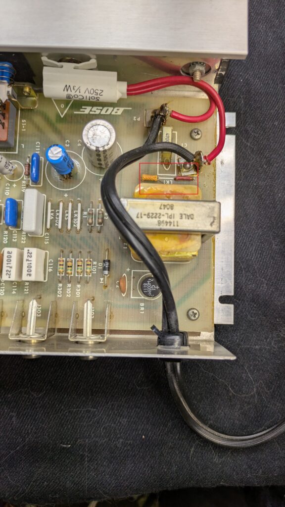
This is the 240 “universal” version with the double primary winding power transformer. Note the 240 VAC sticker on the back panel
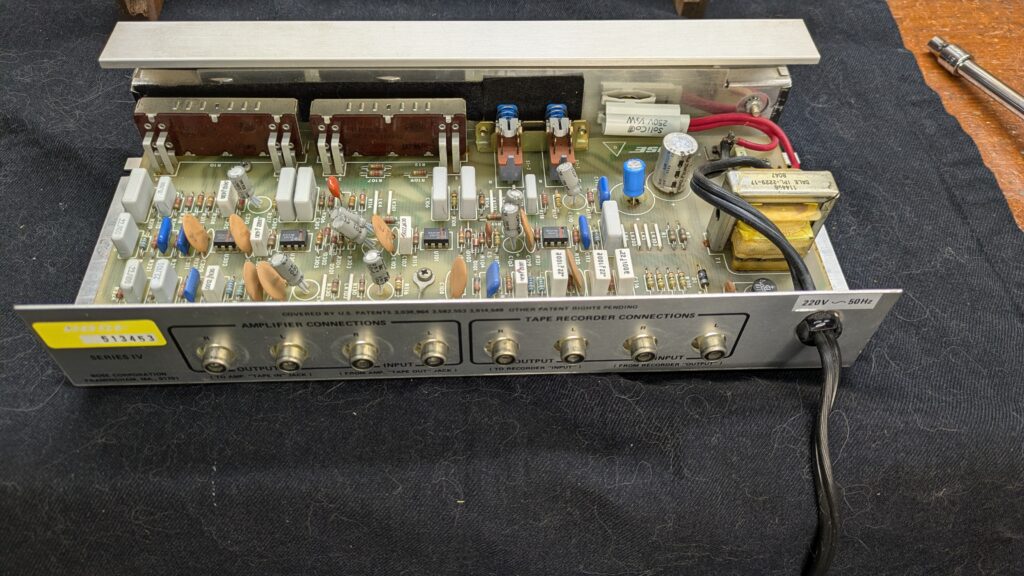
Converts from 120 to 240 VAC by moving a couple of jumpers inside the box. The neon is a 240 VAC unit, which just glows dimmer at 120 VAC.
Here’s the eq family curve set.
Notice the giant THD spike at about 15K on the max control setting; that means the -10 dBV input signal caused the EQ to clip. That could be an issue for some receivers while using the tape loop. A -20 dBV signal didn’t clip at max settings, as expected.
Series VI
I inherited a set of series VI 901s and the EQ. They’re in heavy use at present, at some point I’ll add the VI eq info to this page.
(coming soon)